|
• |
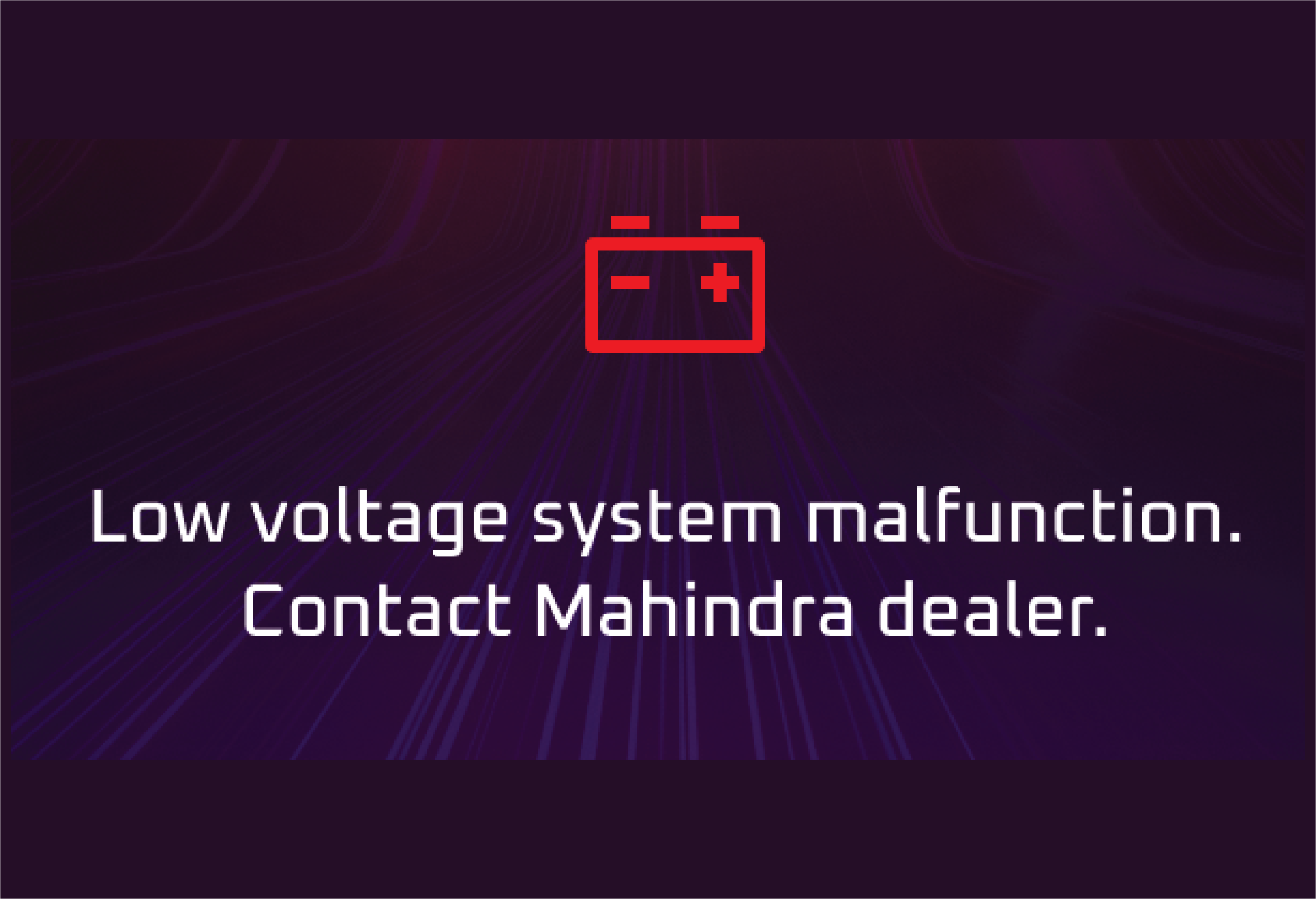
Battery Charge / LV Charge |
The battery charging system warning lamp illuminates when the battery is in a low charge state and not being charged. This
lamp illuminates when the ignition is switched ON and goes out as soon as the vehicle drive is enabled.
Abnormal Operation:
If the lamp continues to remain ON even after enabling the vehicle, it is an indication that the battery is not being charged
or there is a malfunction in the LV charging system.
Actions recommended:
Vehicle battery may not charge, contact a Mahindra Authorised Service Center immediately for assistance.
|
• |
Front Seat Belt Warning Lamp |
Lamp on when ignition is turned on and goes off in few seconds. Lamp remains on when driver seat belt is not worn when vehicle
is running. Chime will also be on reminding driver to wear the seat belt.
Abnormal Operation:
Lamp remains off when driver seat belt is not worn indicates malfunction in the system.
Actions recommended:
Buckle the seat belt and check whether the lamp is turned OFF. If not so, contact a Mahindra Authorised Service Center for
assistance.
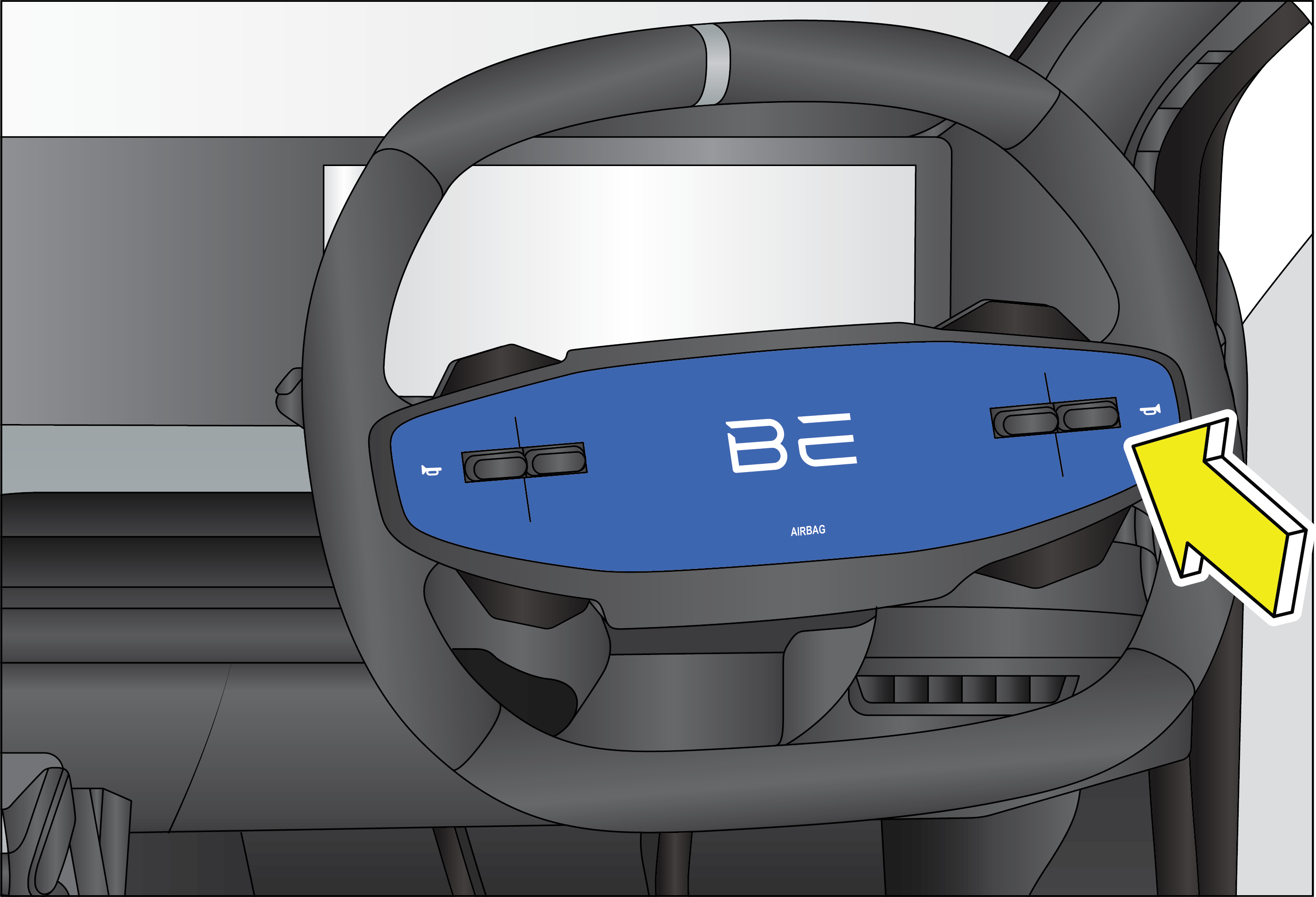
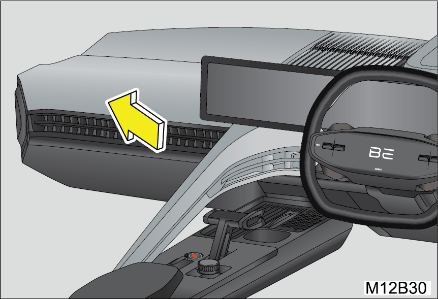
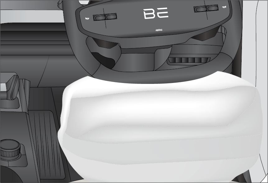
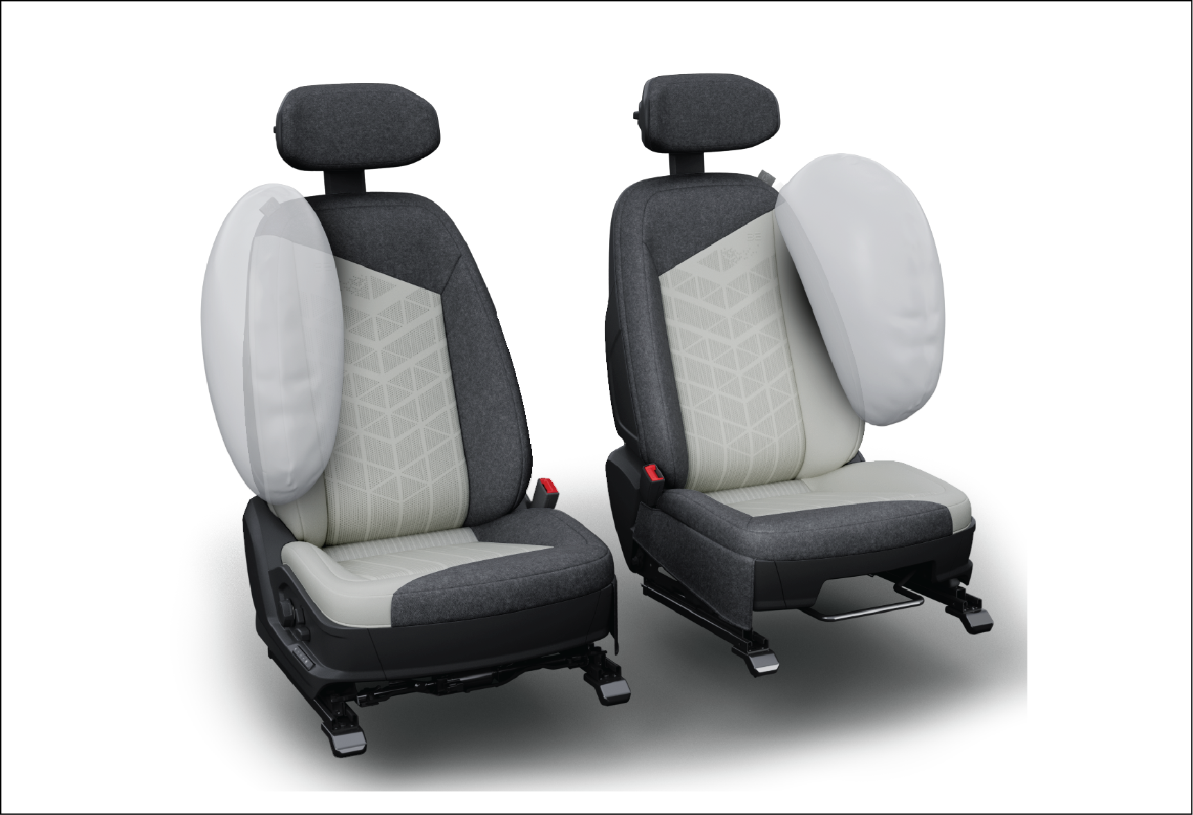
Lamp on when ignition is turned on and goes off in few seconds.
Abnormal Operation:
Lamp continuos on during motor running indicates malfunction in airbag system
Actions recommended:
Airbag may not deploy contact the nearest Mahindra Authorised Service Center for assistance.
Immobiliser Lamp flashes intermittently (few secs. frequency) once the ignition is switched OFF indicating that the vehicle
security system is armed (when locked using the Keyfob).
Abnormal Operation:
Lamp continuously on/ Fast blinking indicates a malfunction in the system.
Actions recommended:
Contact a Mahindra Authorised Service Center immediately.
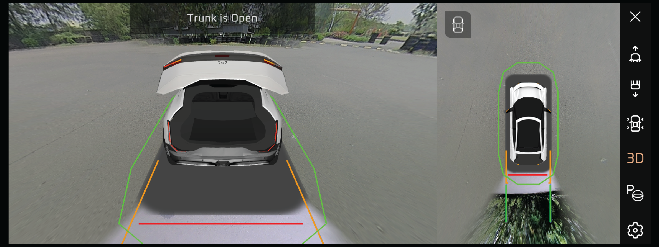
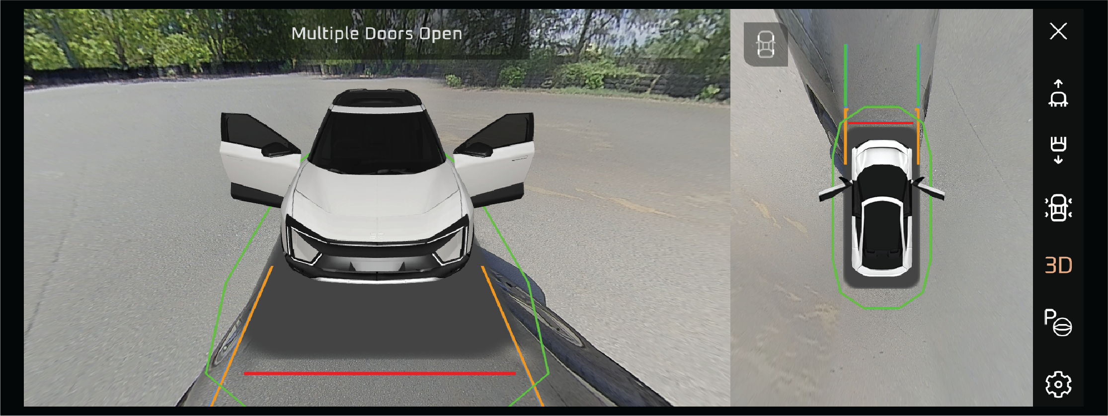
Lamp turns on if any door/hood is open and goes off once it is closed. The buzzer chimes when the vehicle speeds more than
2 kmph. The lamp and chime go OFF when all the doors are closed properly.
Abnormal Operation:
Lamp off when any doors/hood is open or lamp on when all the doors/hood is closed indicates malfunction.
Actions recommended:
Open and close all the doors/hood and check whether the warning lamp is working as intended. If not, then contact a Mahindra
Authorised Service Center for assistance.
|
• |
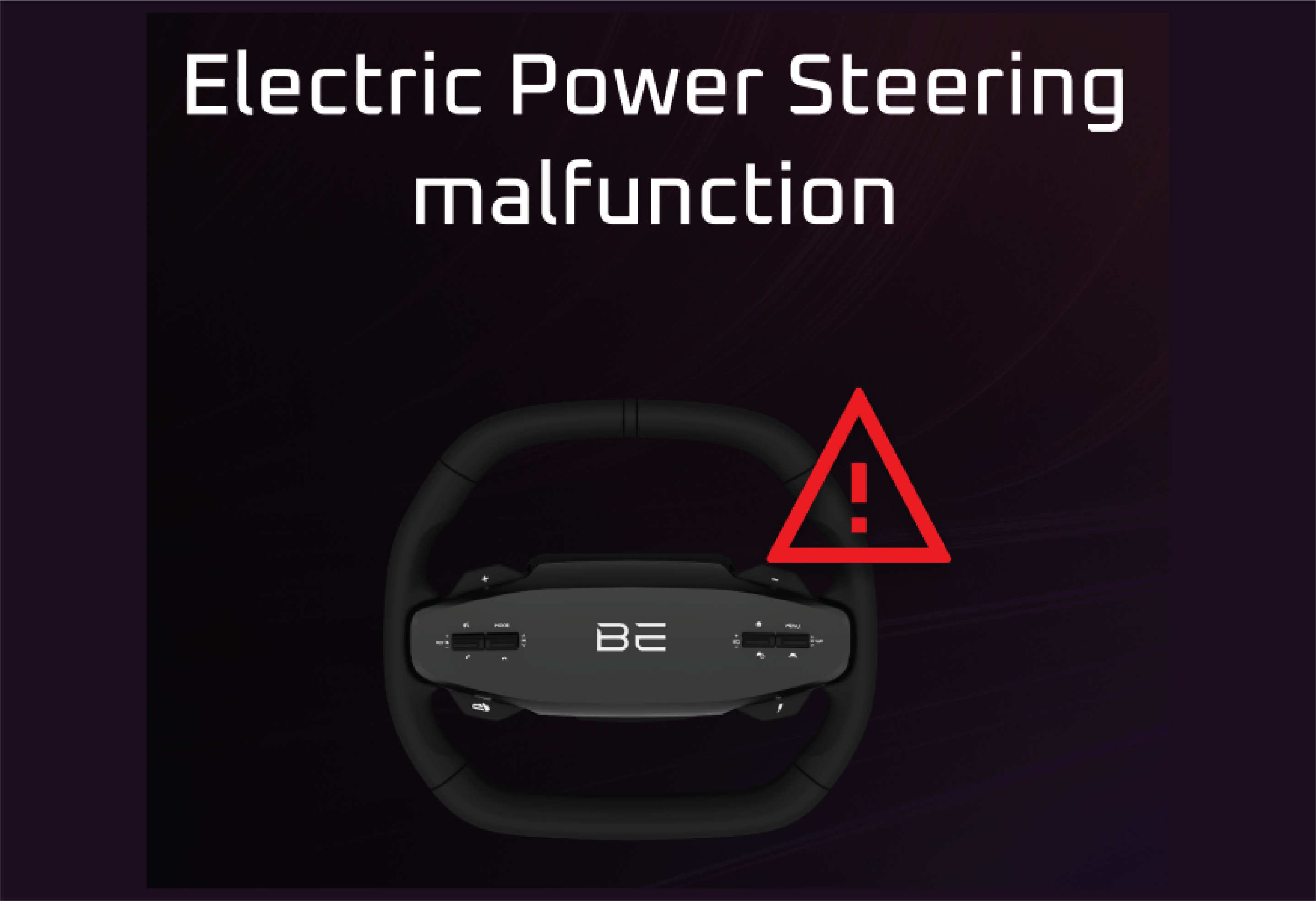
Electronic Power Steering System (EPS) Warning Lamp |
The EPS warning lamp illuminates when the ignition is switched ON and goes OFF after about 3 secs.
Abnormal Operation:
Lamp continuously on Indicates malfunction in Electric Power steering system which may result in hard power steering system.
Actions recommended:
Steering may be hard to steer, drive the vehicle to the nearest Mahindra Authorised Service Center.
|
• |
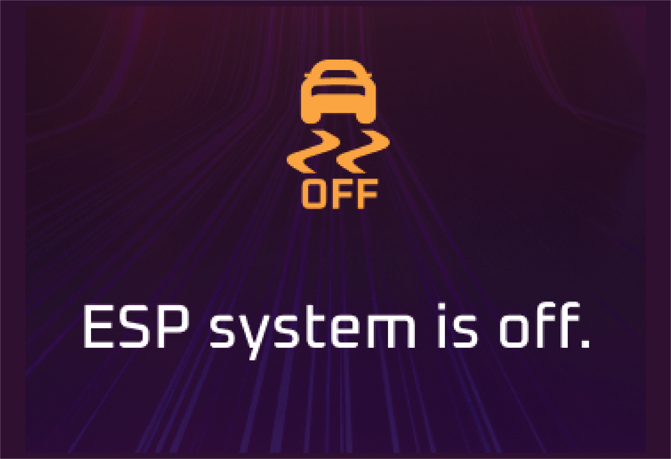
Electronic Stability Control (ESC) OFF |
Lamp on when ignition is turned on and goes off in few seconds.
Abnormal Operation:
Lamp not turning on/off when ESC OFF switch is operated indicates malfunction in the ESC system.
Actions recommended:
ESC function may not work contact the Mahindra Authorised Service Center .
|
• |
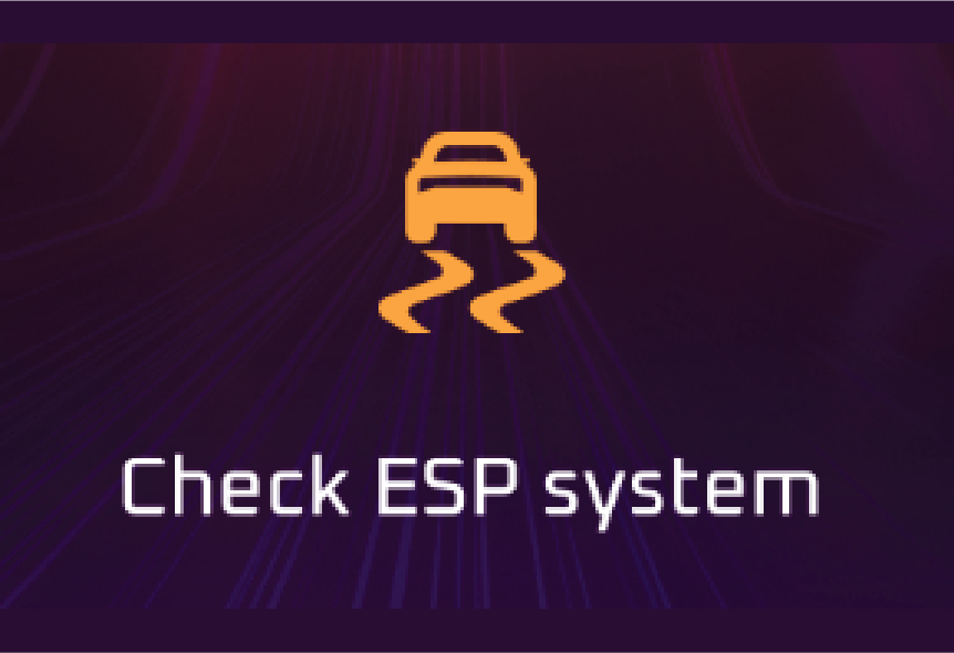
Electronic Stability Control (ESC) Malfunction Warning Lamp |
Lamp on when ignition is turned on and goes off in few seconds.
Abnormal Operation:
While driving, if the ESC system warning lamp blinks, it indicates that ESC has taken control of the vehicle stability. If
the lamp remains ON, it indicates the malfunction in the ESC System.
Actions recommended:
If ESP function doesn't work Then Contact the Mahindra Authorised Service Center .
|
• |
Anti-lock Braking System (ABS) Warning Lamp |
Lamp on when ignition is turned on and goes off in few seconds.
Abnormal Operation:
If the lamp remains ON while driving indicates the malfunction in the System.
Actions recommended:
Then Contact the Mahindra Authorised Service Center.
|
• |
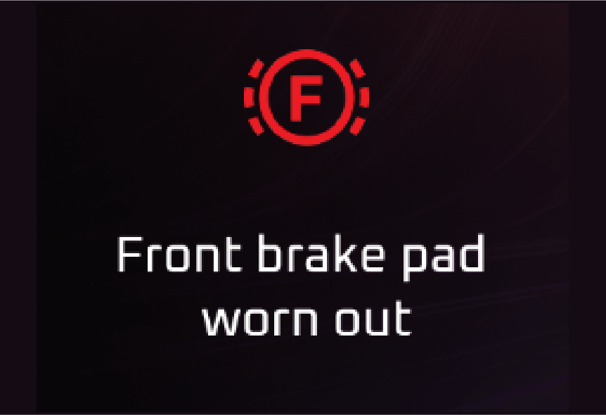
Electronic Brakeforce Distribution (EBD) / Brake Malfunction/Park Brake |
Lamp on when ignition is turned on and goes off in few seconds or when parking brake is disengaged.
Abnormal Operation:
Lamp continuously on indicates Brake fluid level might be low/ malfunction in parking brake system/Front Brake Pad worn out.
Actions recommended:
Either one of the below conditions:
| 1. |
|
Park Brake is engaged. |
| 2. |
|
Brake fluid level is low. Check & top up if required. If issue still persists, contact an authorised Mahindra Dealer. |
| 3. |
|
There is some concern in EBD. Please contact Mahindra Authorised Service Center. |
| 4. |
|
Integrated Electronic Booster Malfunction/Error. Please contact Mahindra Service Center |
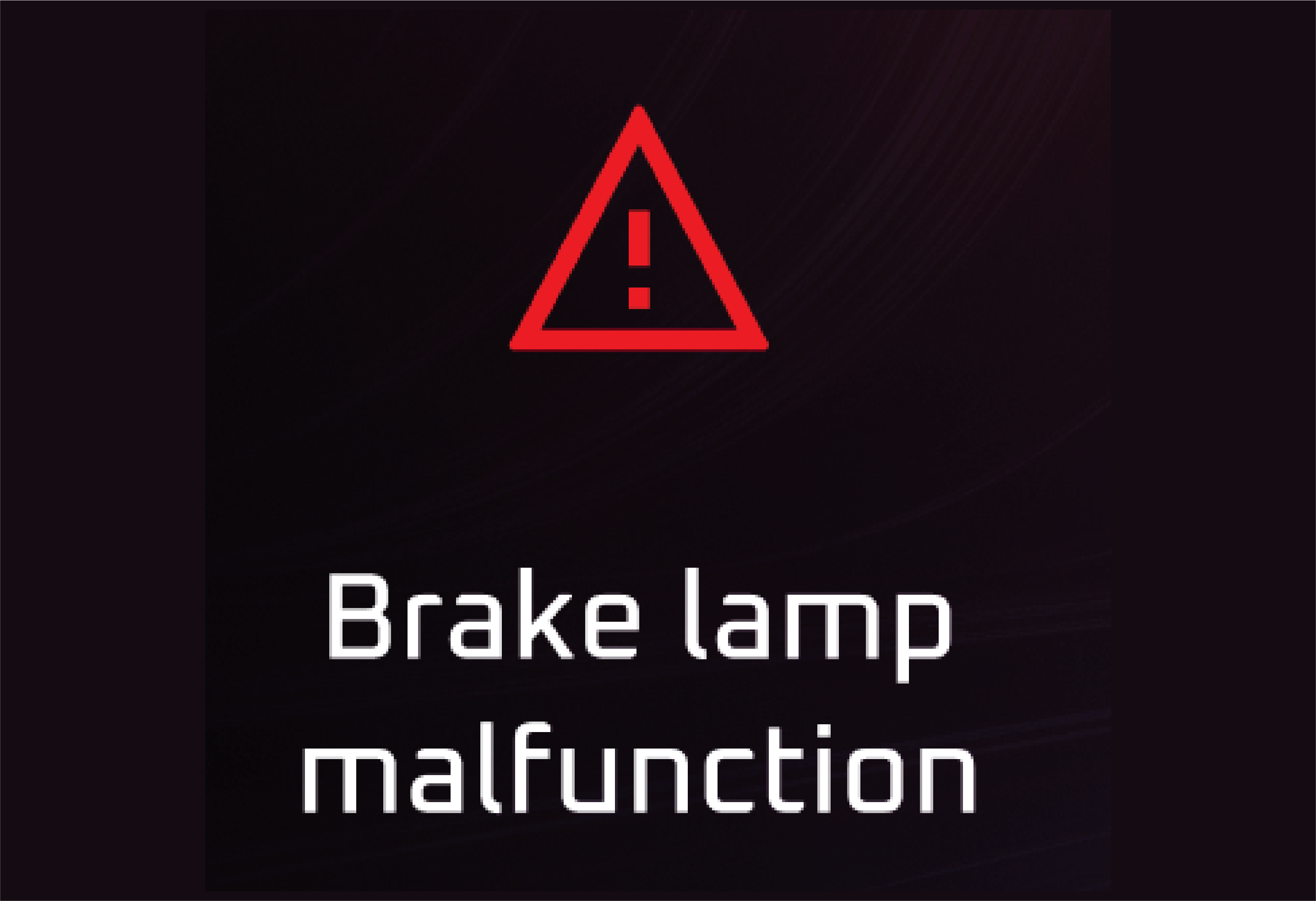
Lamp on when the head lamps are switched ON to high beam or when the head lamp flash is used and goes off when High beam lamp
is turned off
Abnormal Operation:
Lamp not working on/off when head lamp high beam is on/off indicates malfunction in the system.
Actions recommended:
In case of any malfunction, immediately contact the nearest Mahindra authorised service centre.
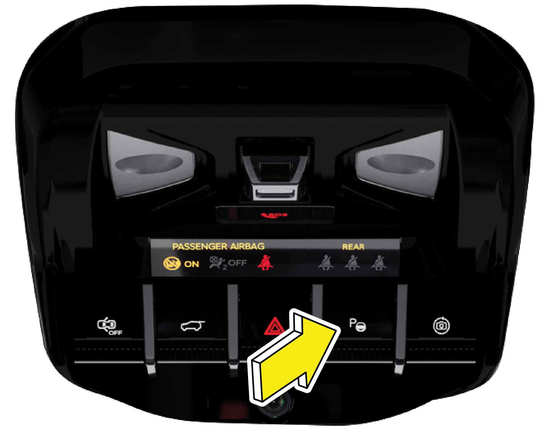
The Park lamp indicator illuminates whenever park lamp is switched ON through Combination switch. During ignition OFF, if
park lamp is already ON with driver door open, alert will be displayed.
Abnormal Operation:
Lamp not turning ON/OFF when park lamp is on/off indicates malfunction in the system
Actions recommended:
Park lamp need to be checked, In case of any malfunction, immediately contact the nearest Mahindra authorised service centre.
|
• |
Front Fog Lamp Indicator |
Lamp on/off when both the front fog lamp and the parking lamps are turned on/off
Abnormal Operation:
Lamp not turning on/off when the front fog lamp turned on/off indicates the malfunction in the system.
Actions recommended:
Fog lamp may not work, In case of any malfunction, immediately contact the nearest Mahindra authorised service centre.
Lamp blinks whenever left turn indicator is turned ON or hazard lamp is ON.
Abnormal Operation:
Lamp blinks /flashing in higher rate indicates failure in one or more of the lamp bulbs.
Actions recommended:
In case of any malfunction, immediately contact the nearest Mahindra authorised service centre.
Lamp blinks whenever right turn indicator is turned on or hazard lamp is on.
Abnormal Operation:
Lamp blinks /flashing in higher rate indicates failure in one or more of the lamp bulbs.
Actions recommended:
In case of any malfunction, immediately contact the nearest Mahindra authorised service centre.
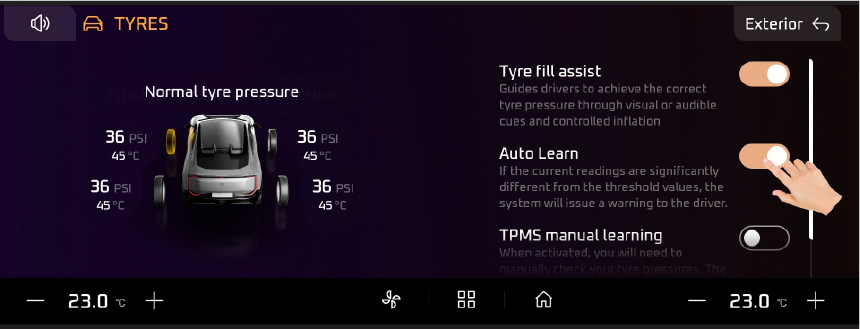
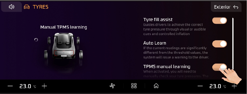
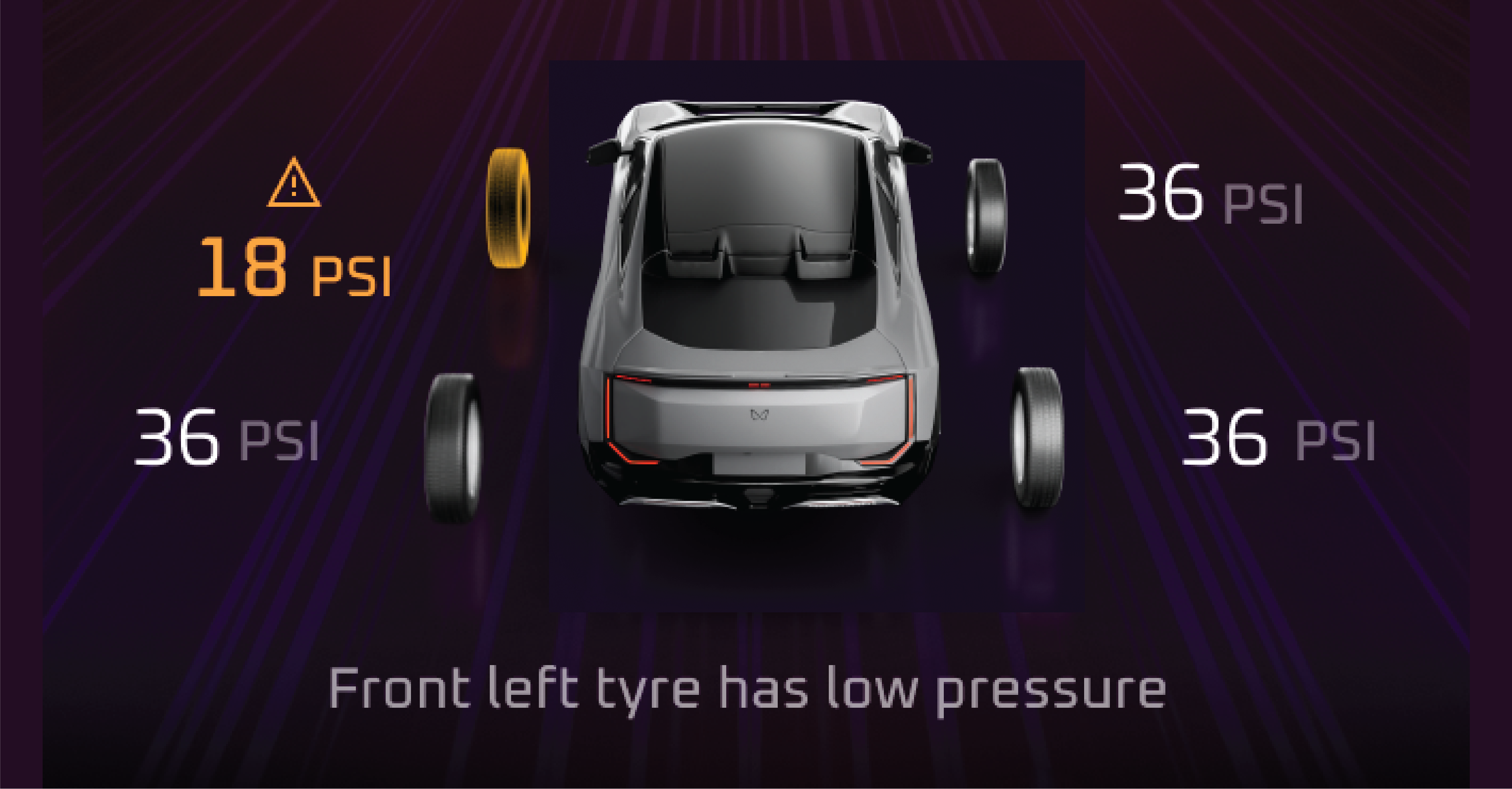
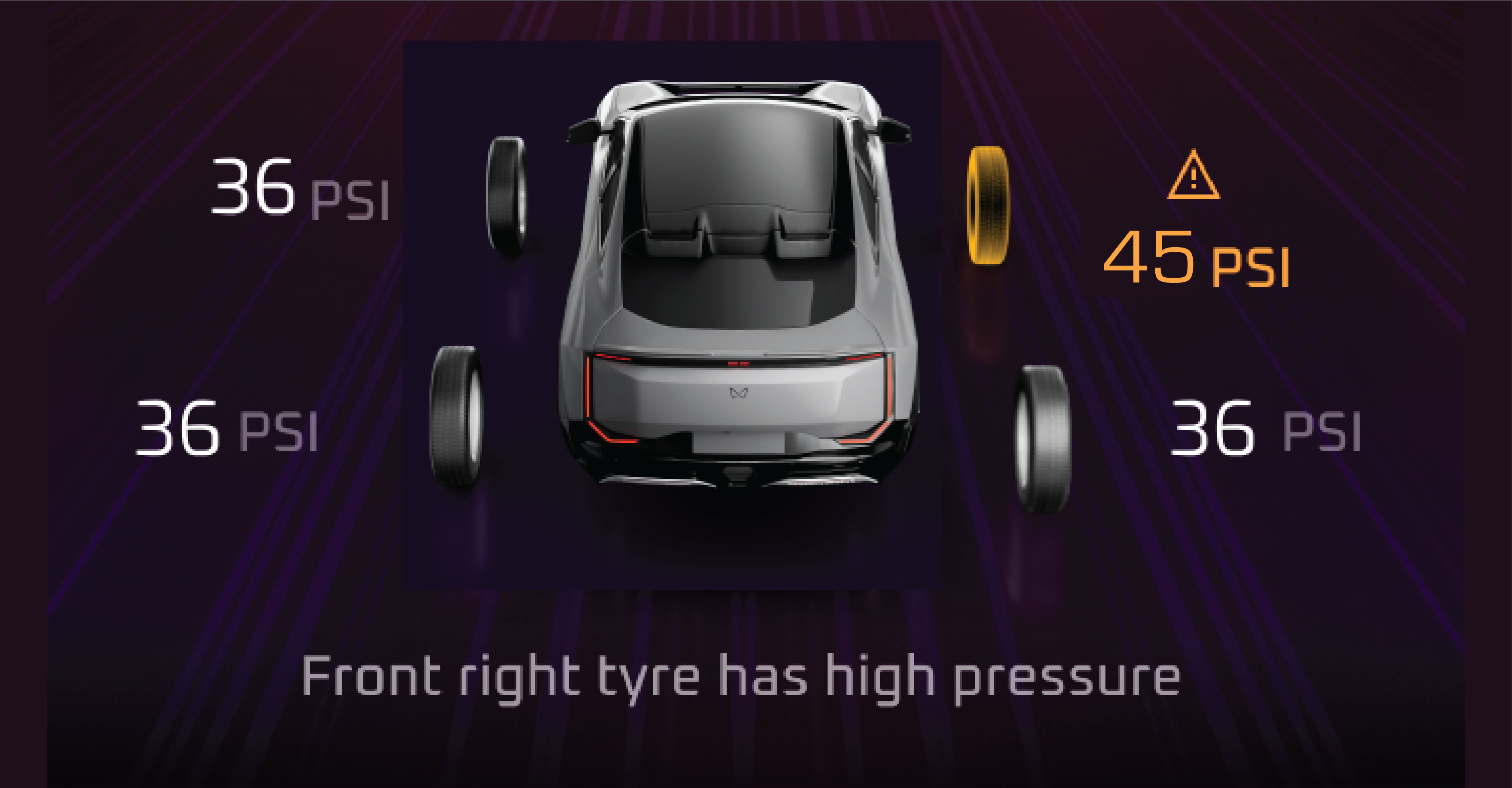
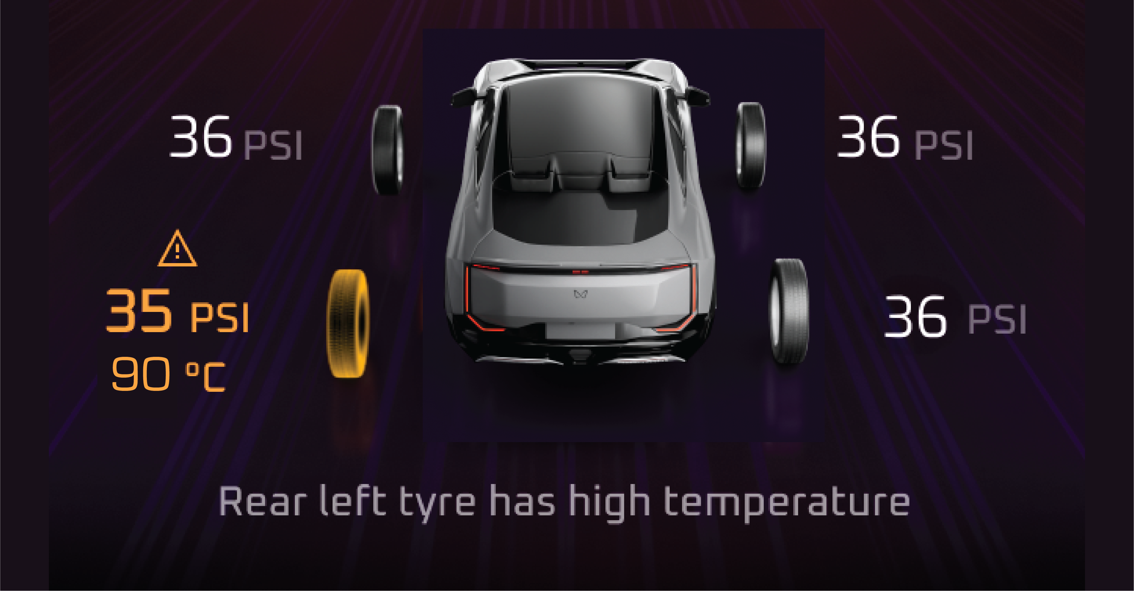
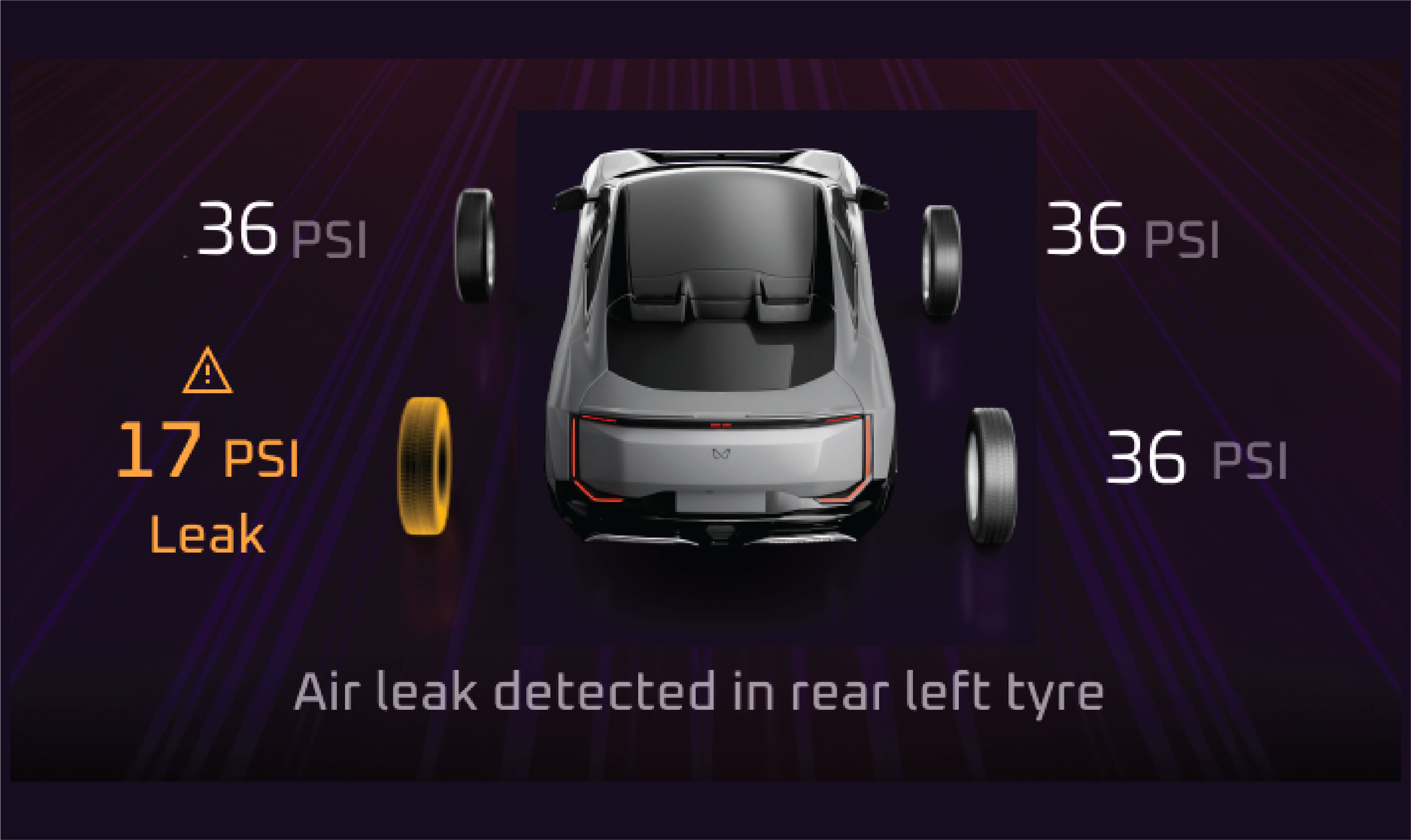
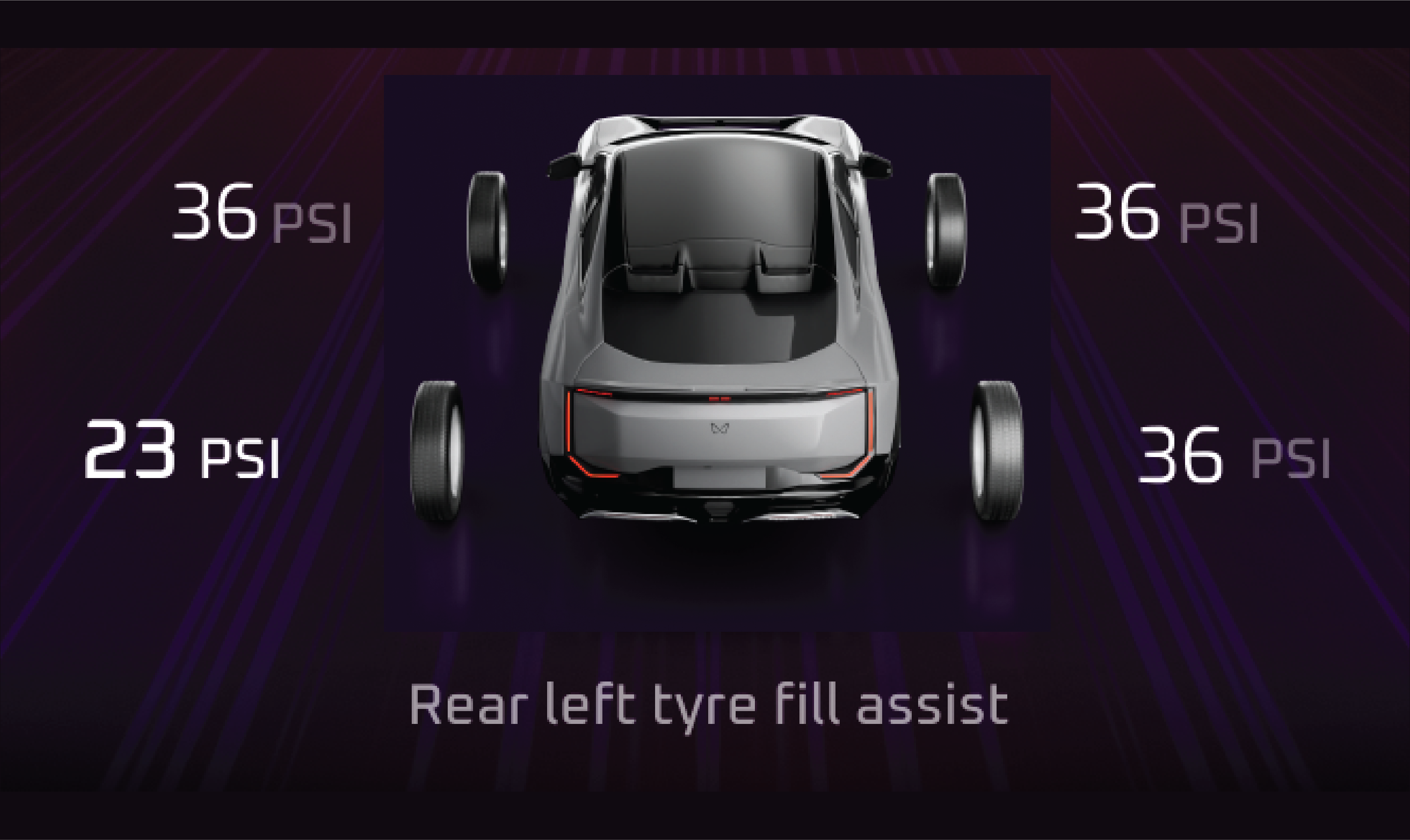
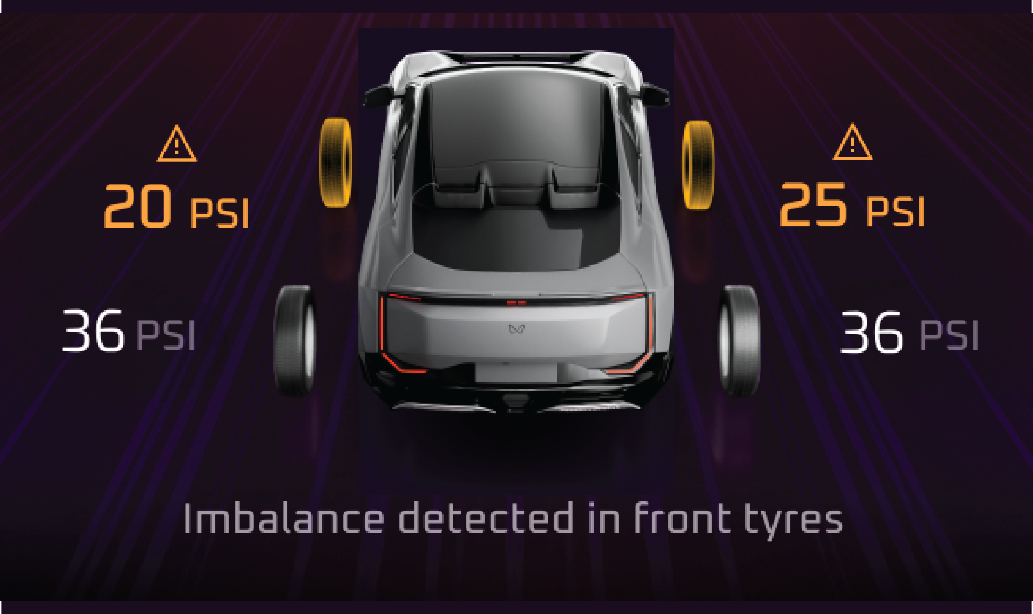
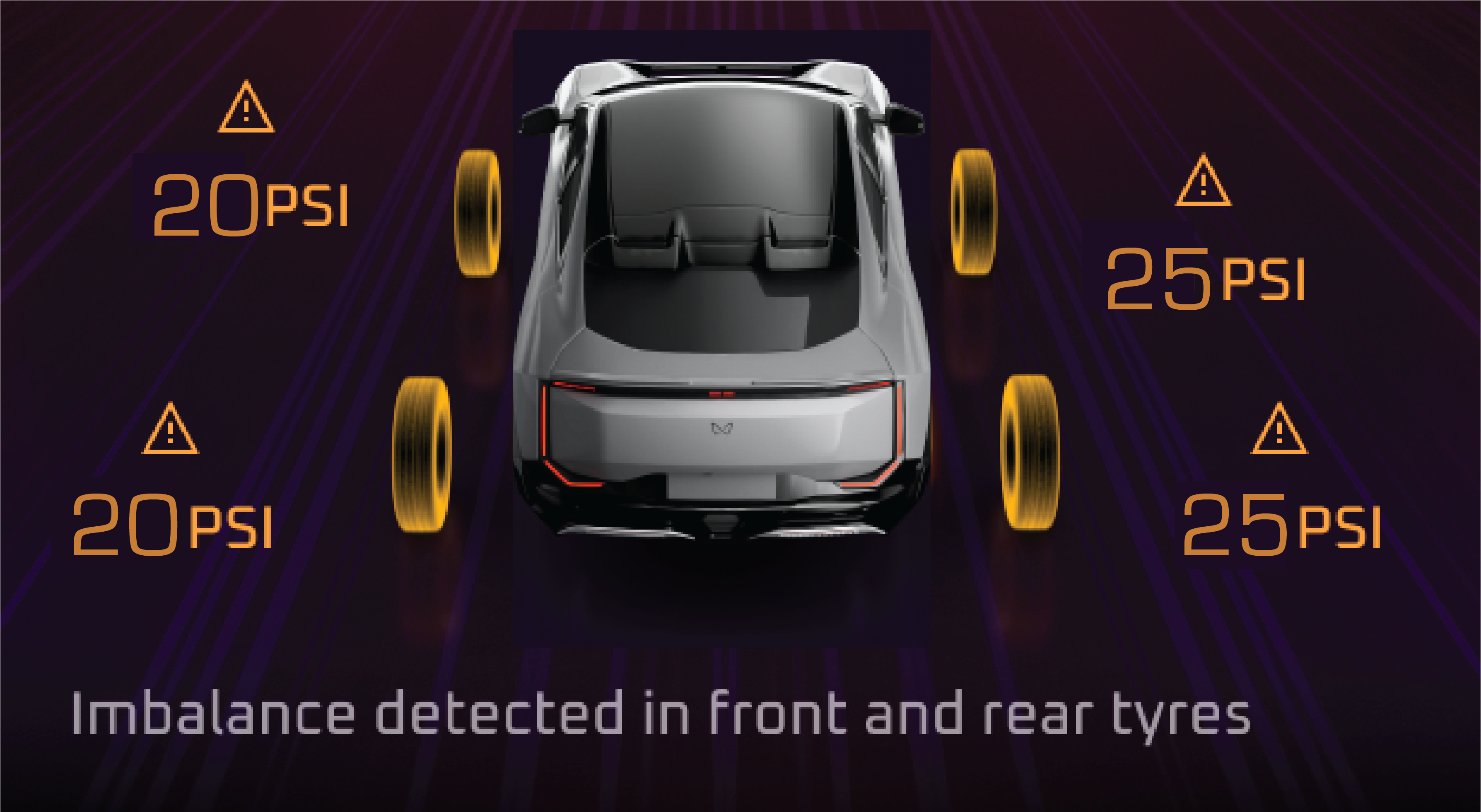
Lamp on when ignition is turned on and goes off in few seconds.
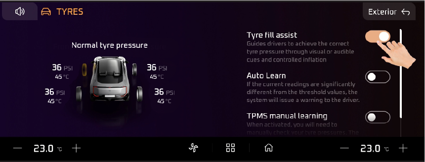
Abnormal Operation:
Lamp continuously on indicates the Tire pressure falls below the low pressure or raises above high pressure/ air leakage/high
temperature Lamp blinks for 90 seconds and then continuously on indicates tiretronics system malfunction.
Actions recommended:
Inspect and adjust the tire pressure and check for the lamp, if still ON then contact the Mahindra authorized Service Center
for assistance.
|
• |
Hill Hold Control (HHC) Malfunction |
Lamp on when ignition is turned on and goes off in few seconds.
Abnormal Operation:
Lamp continuously on indicates malfunction in HHC system.
Actions recommended:
If the warning lamp is turned on, have the vehicle checked and serviced at a Authorized Mahindra Service center.
|
• |
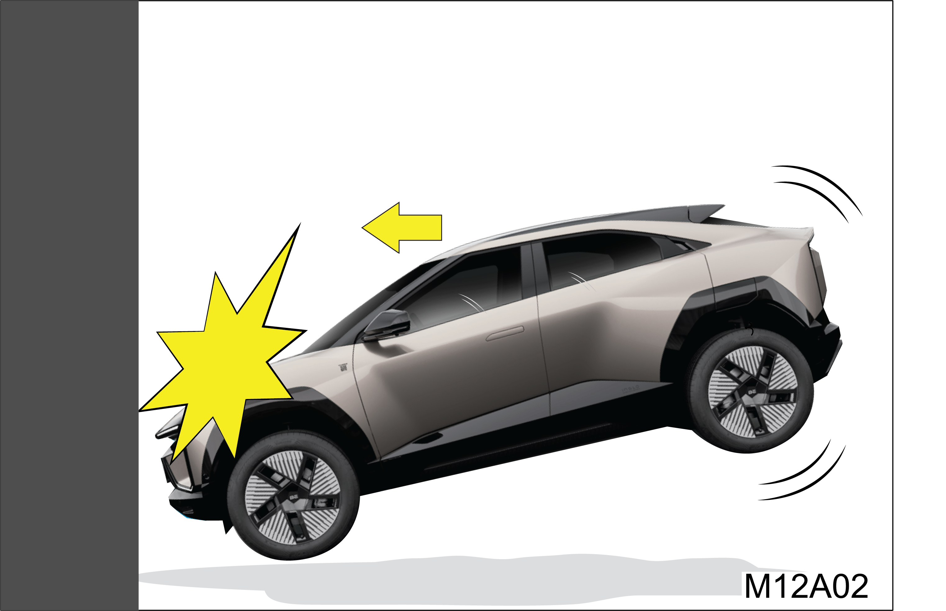
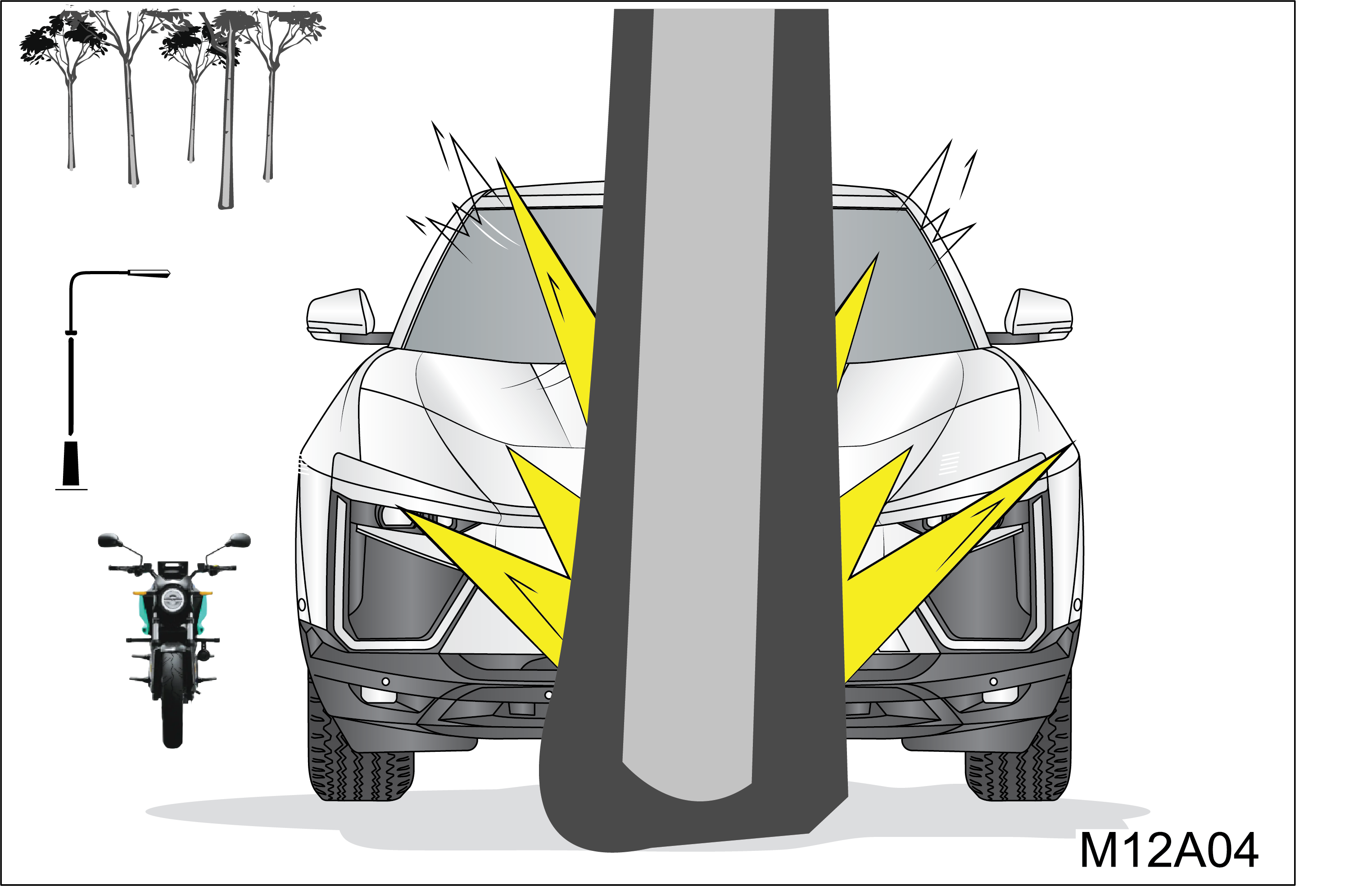
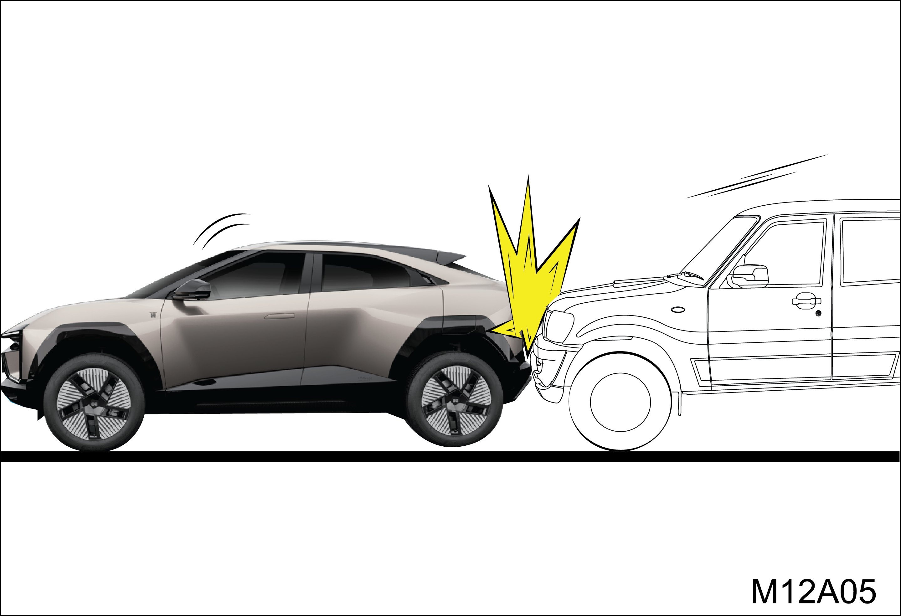
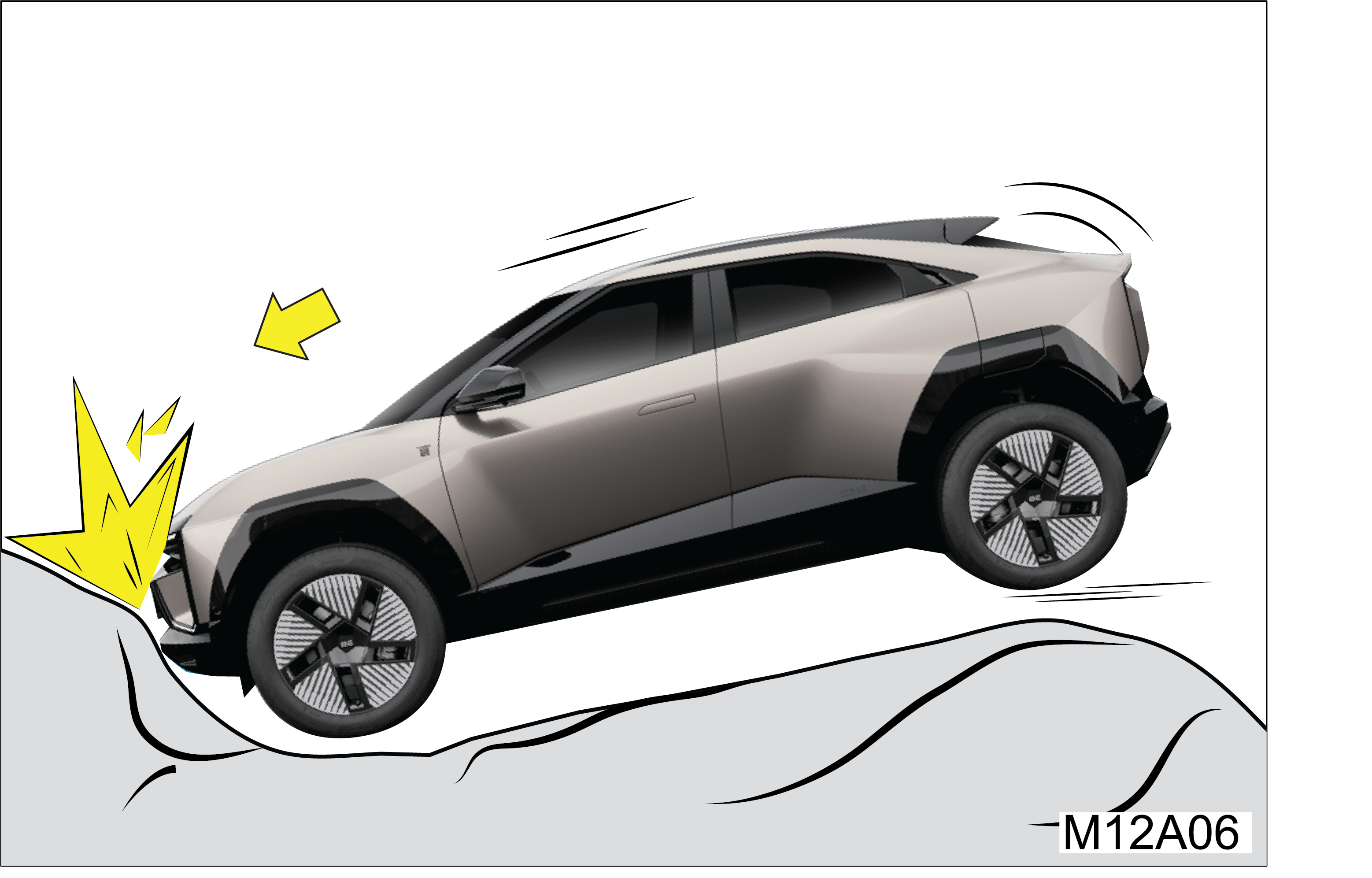
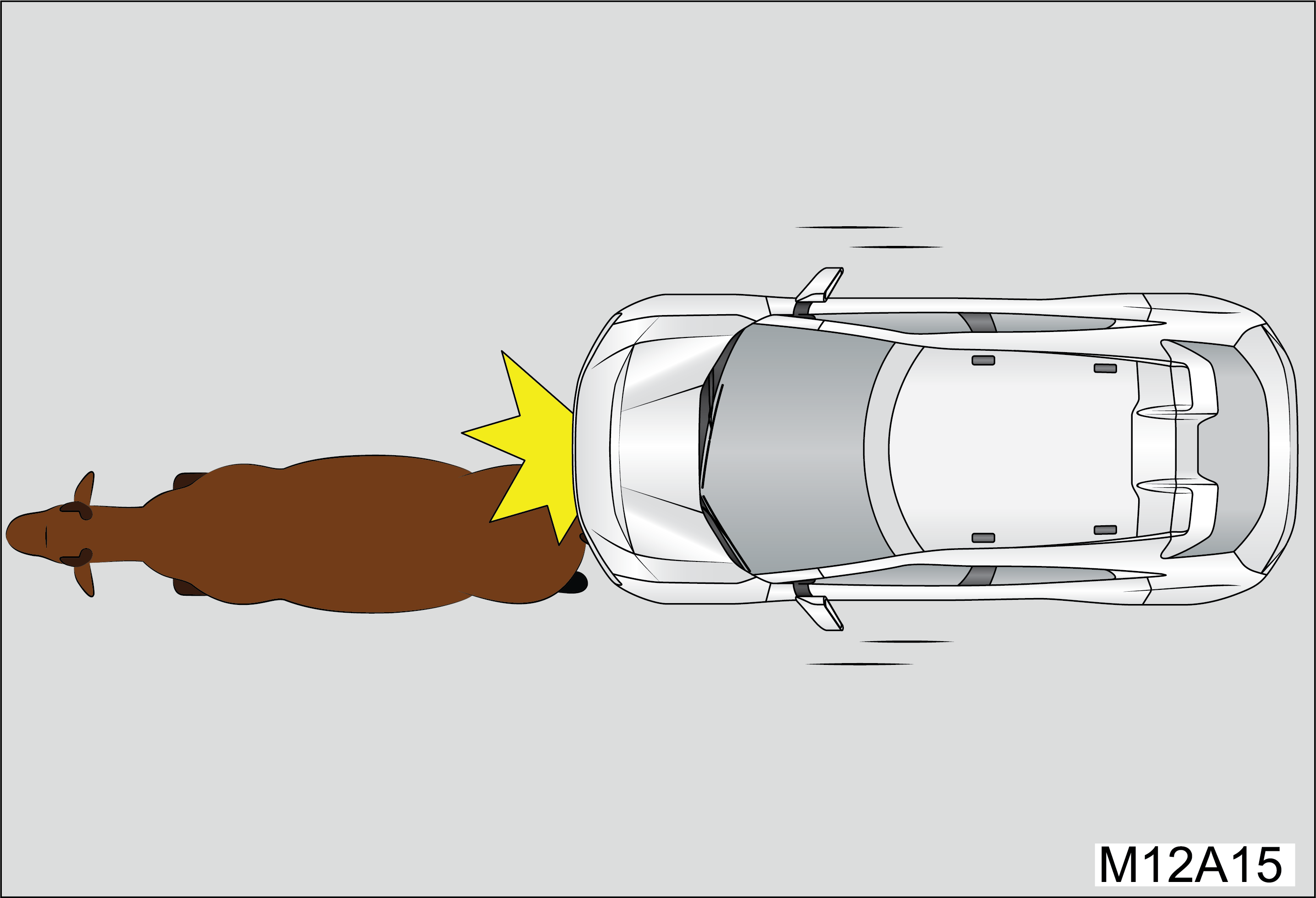
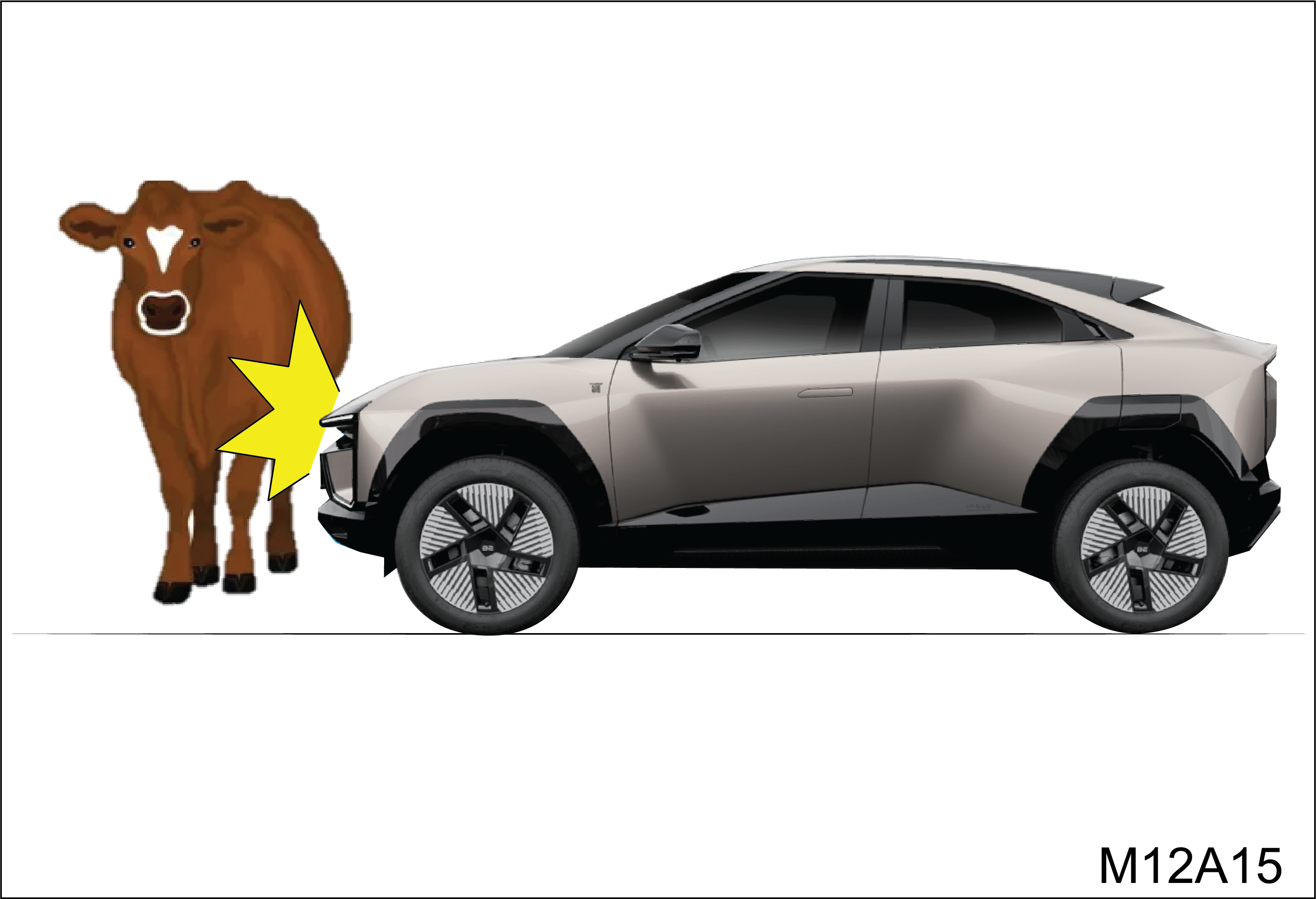
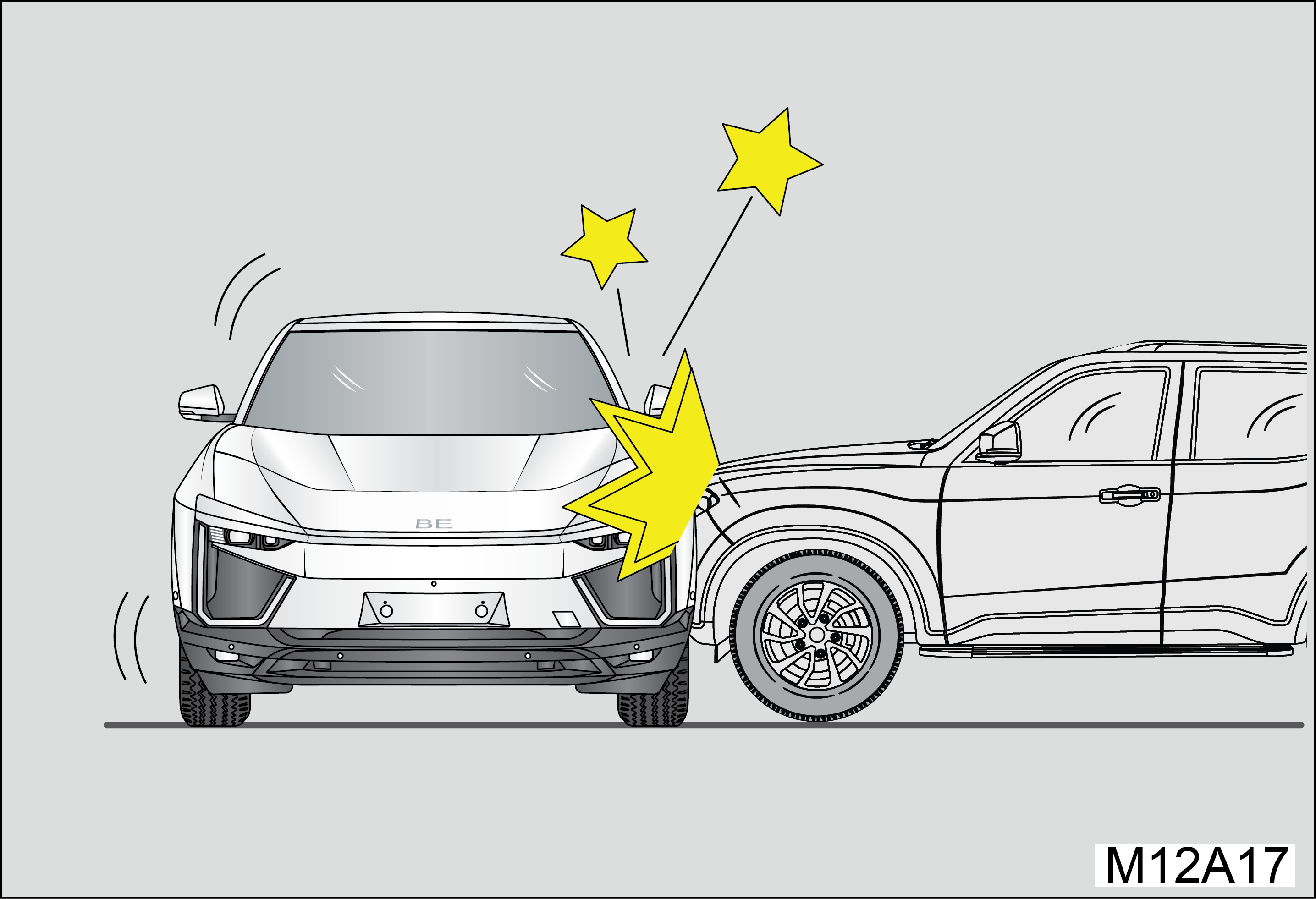
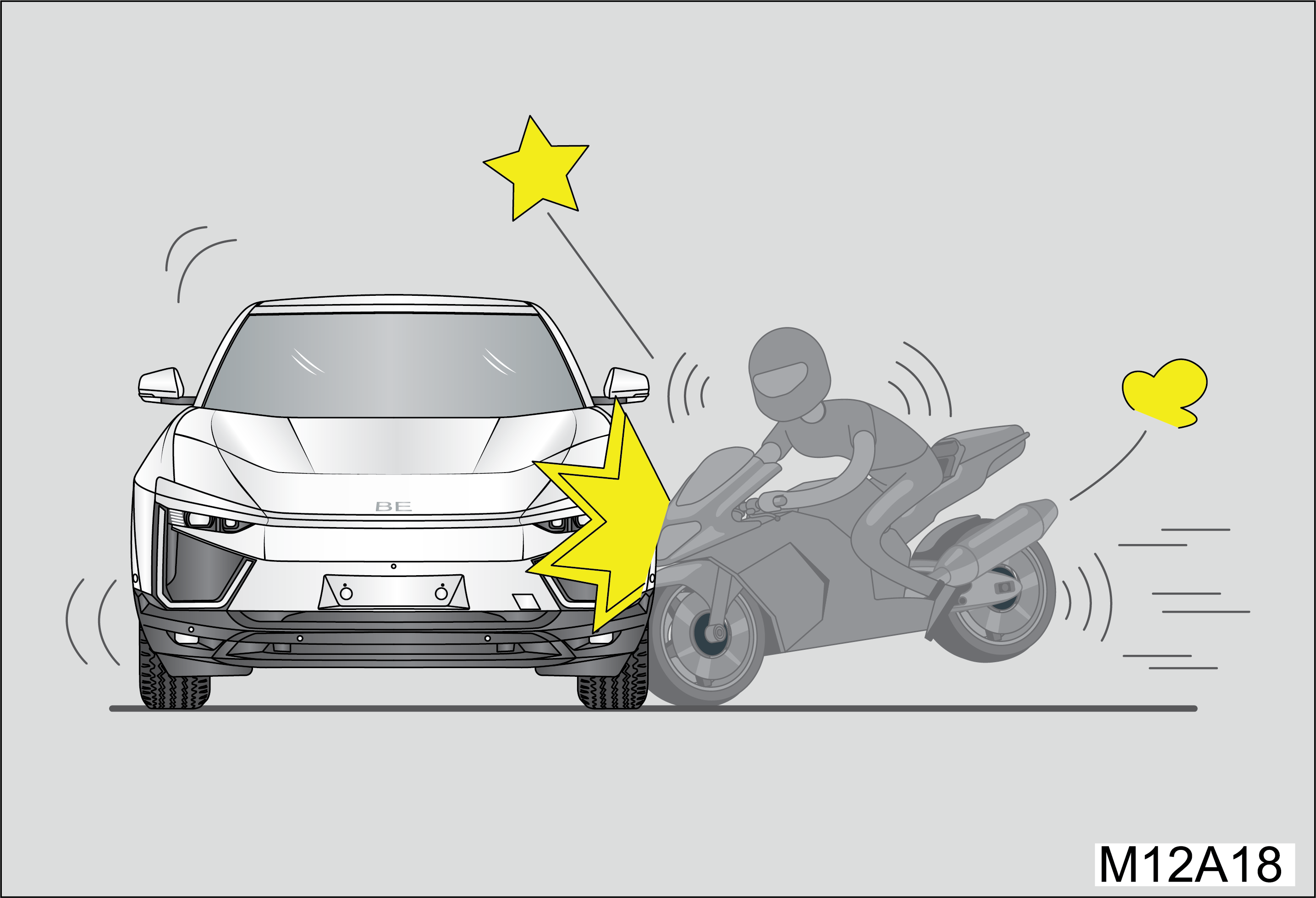
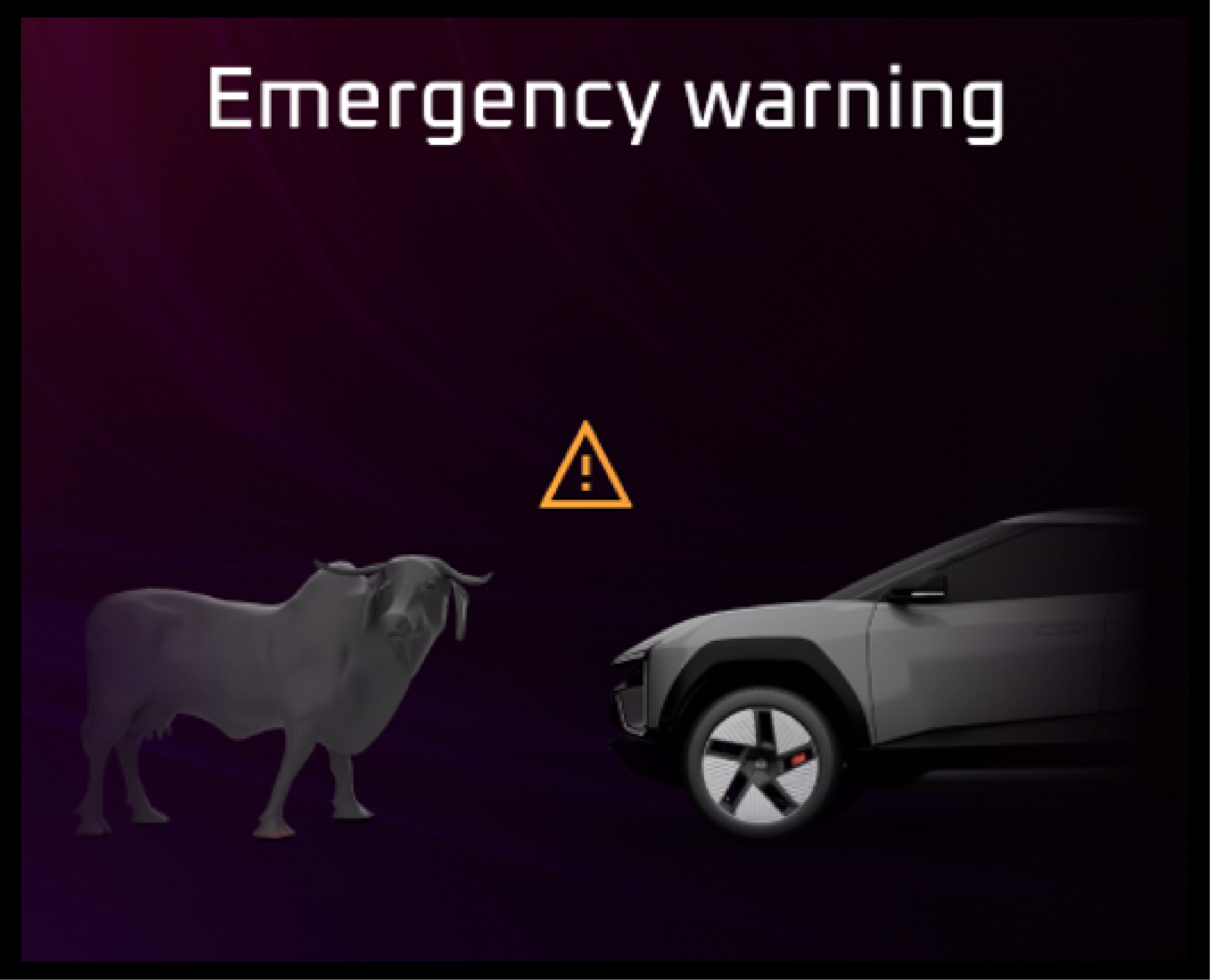
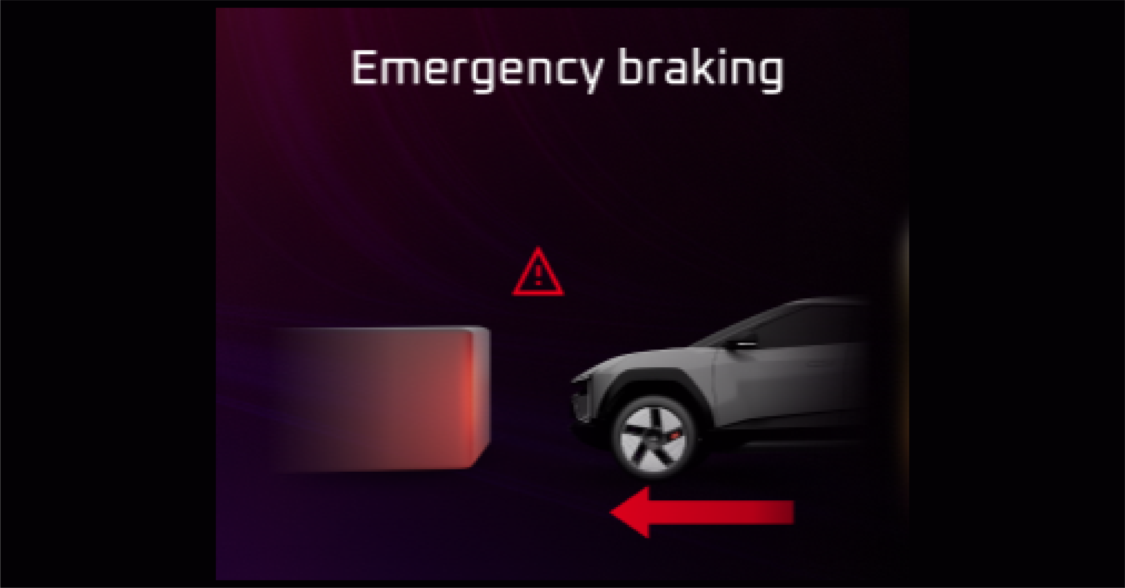
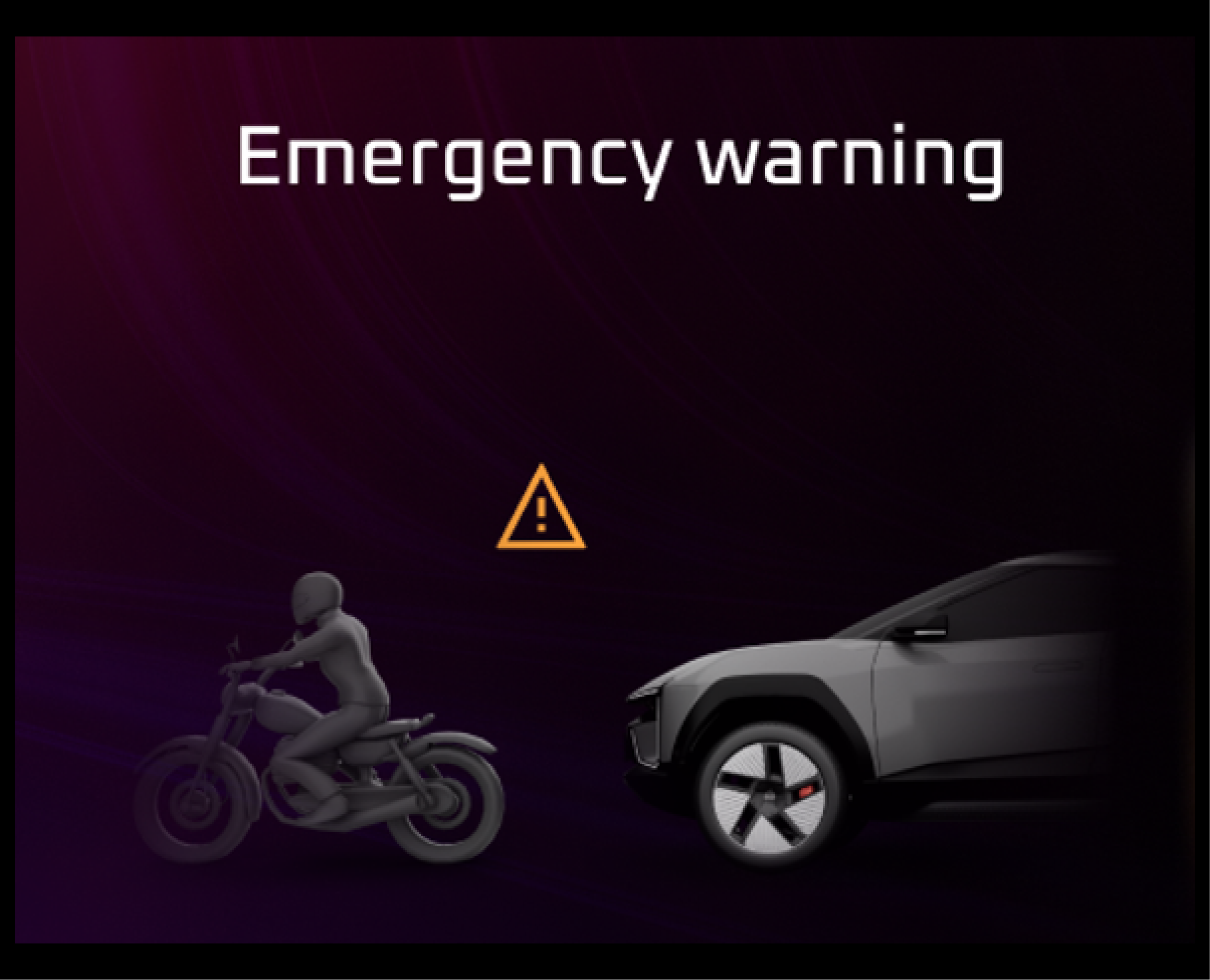
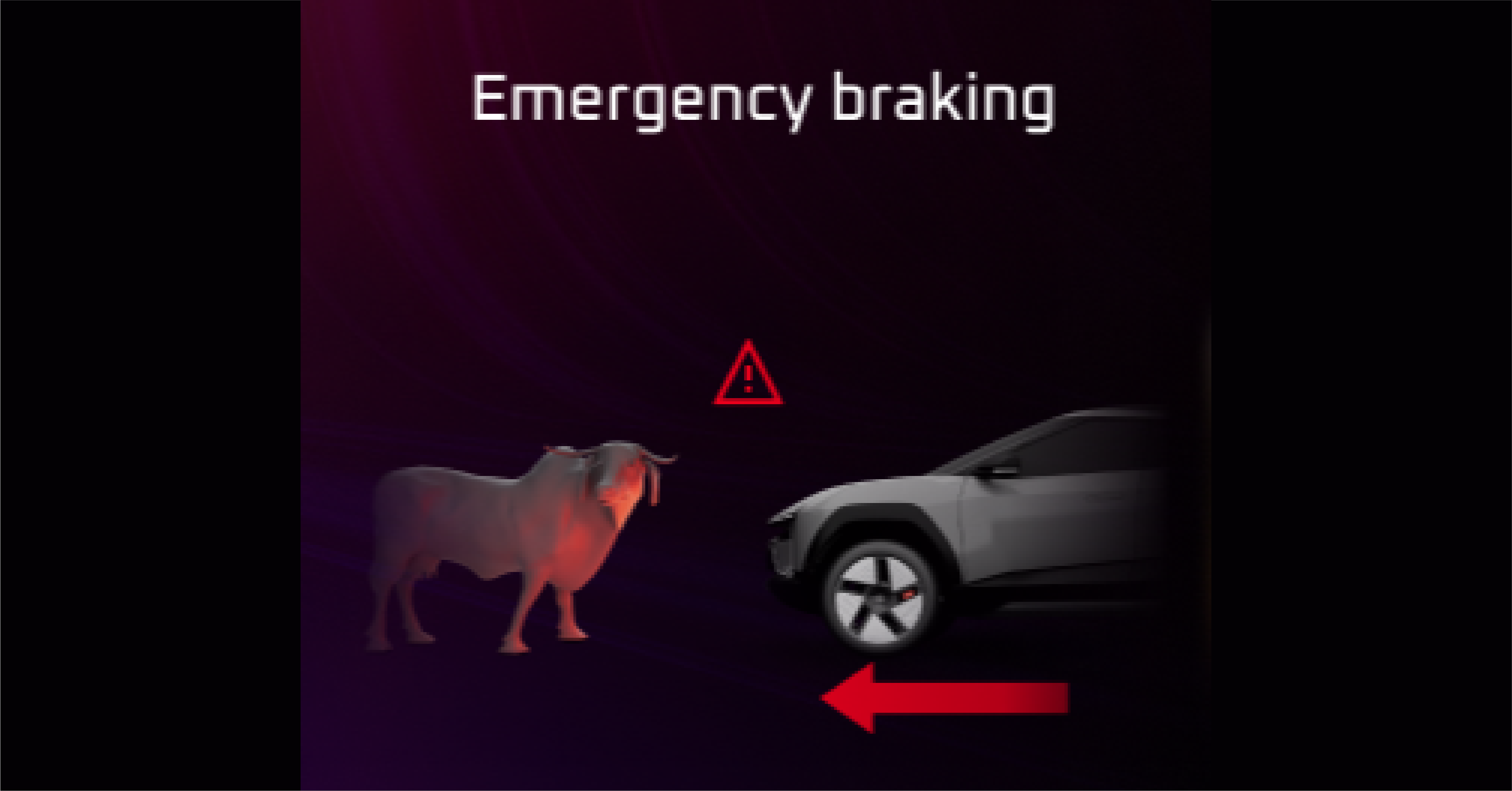
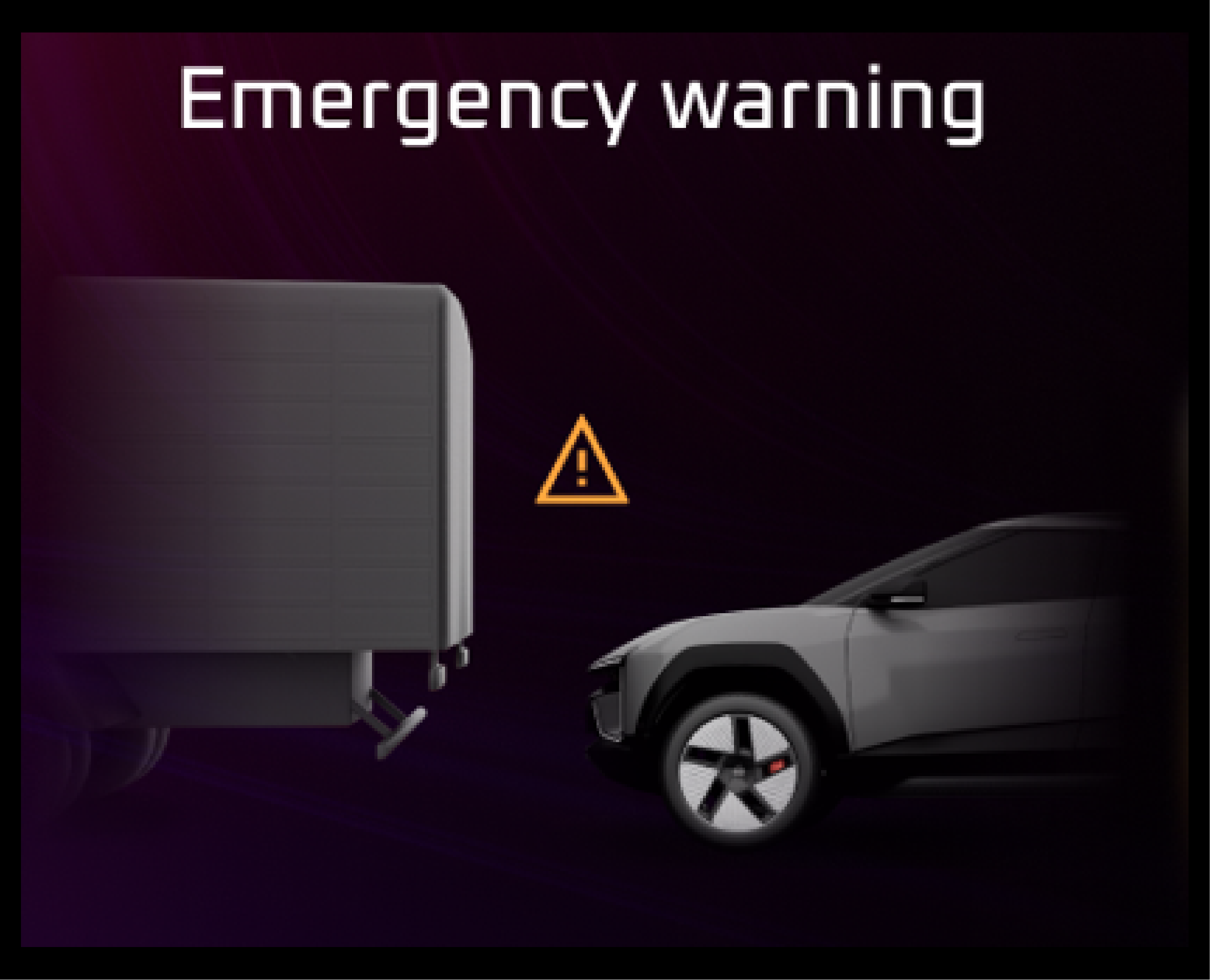
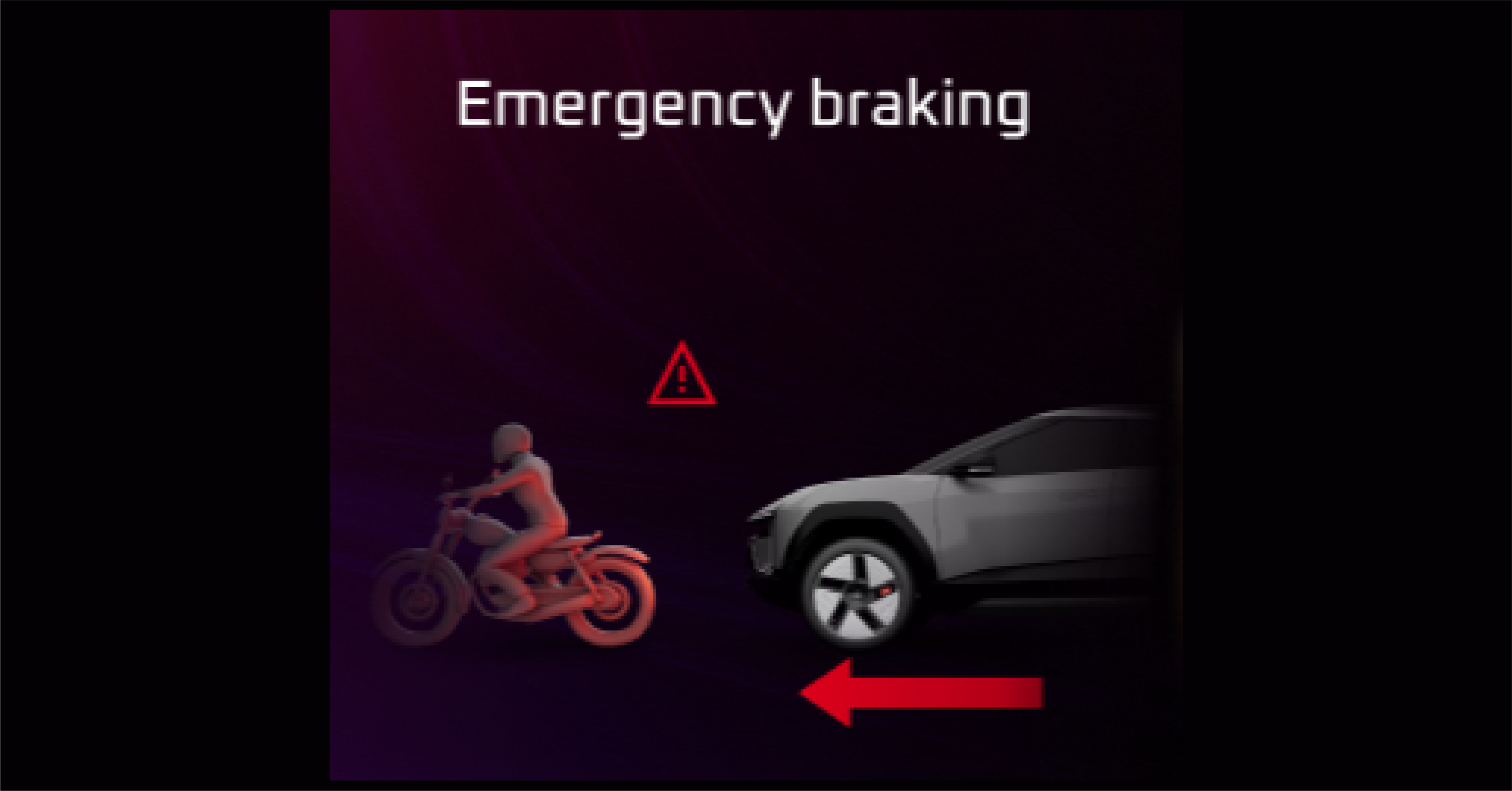
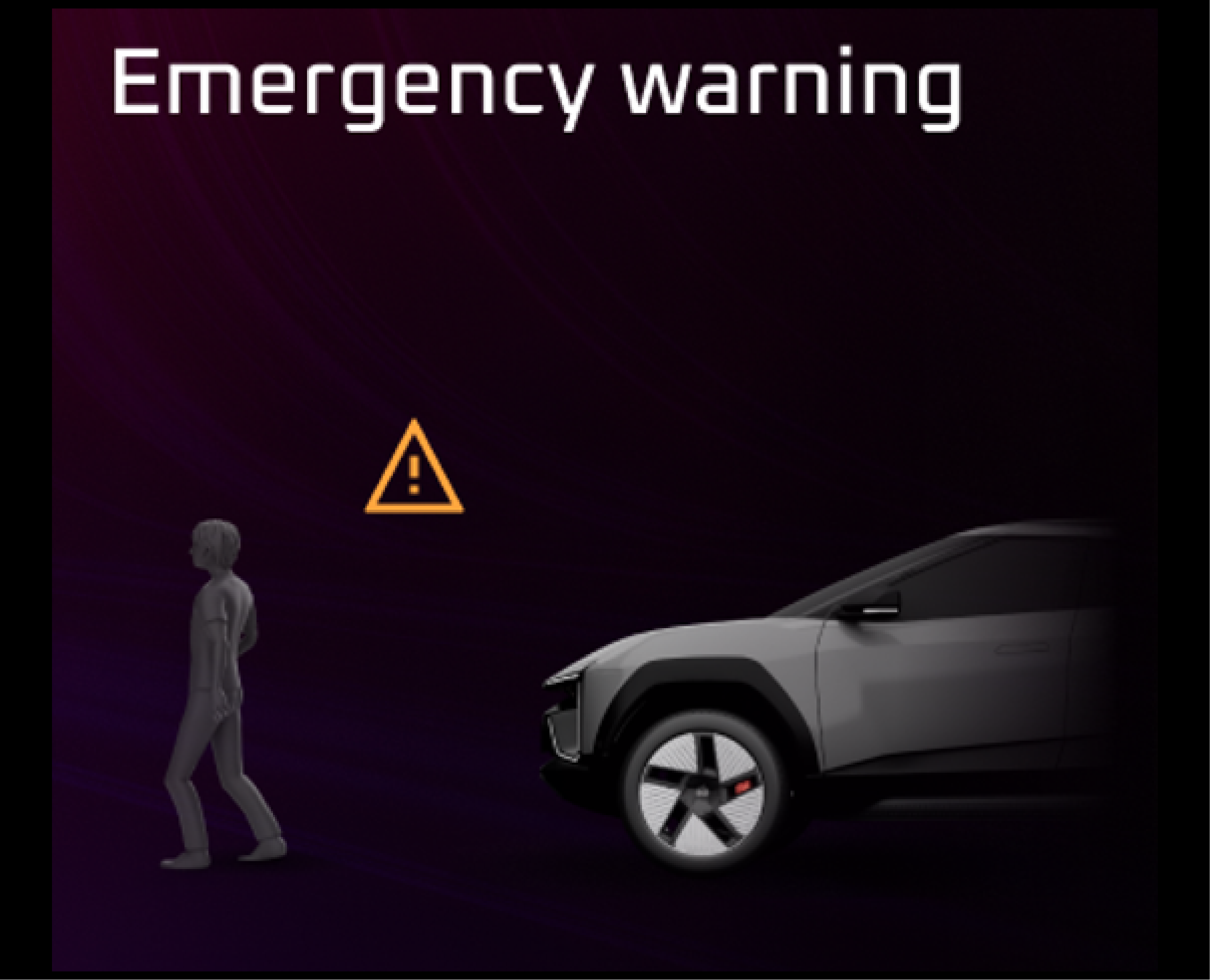
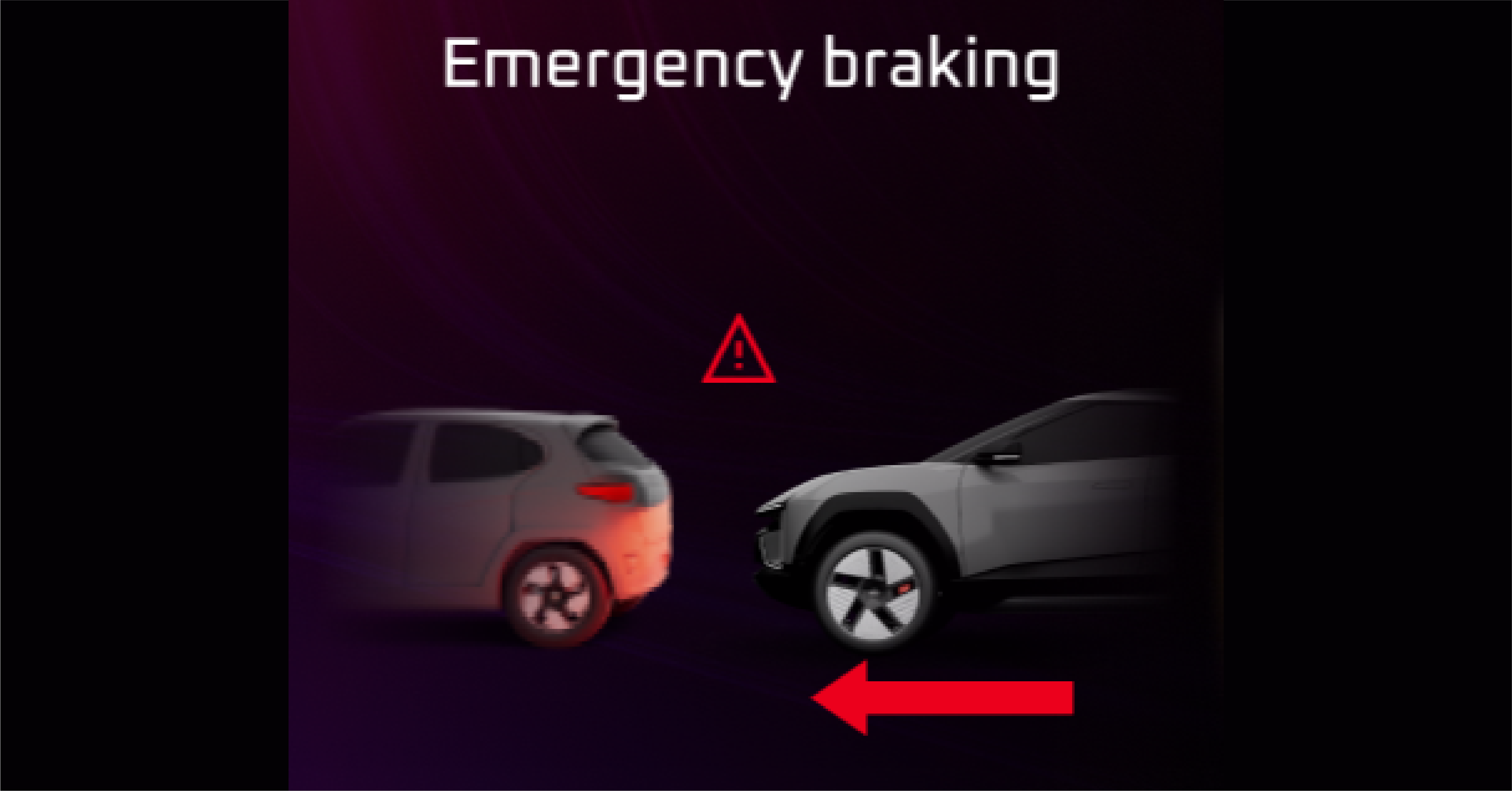
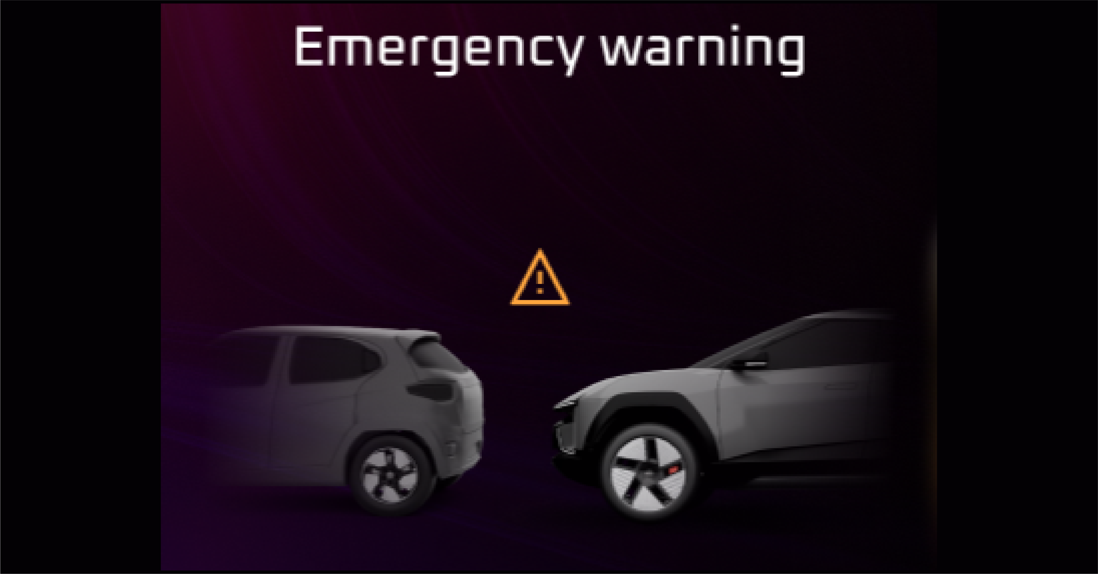
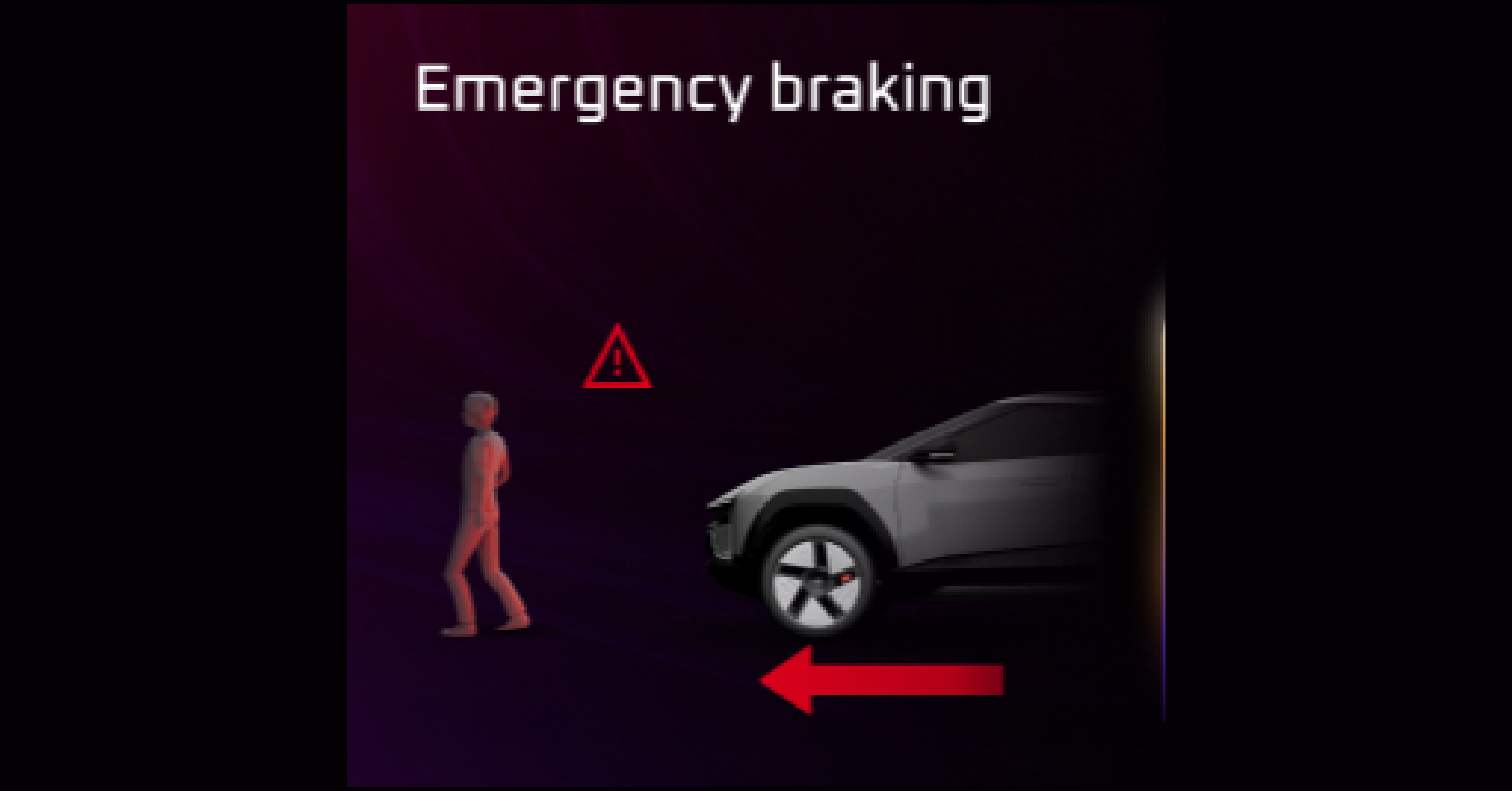
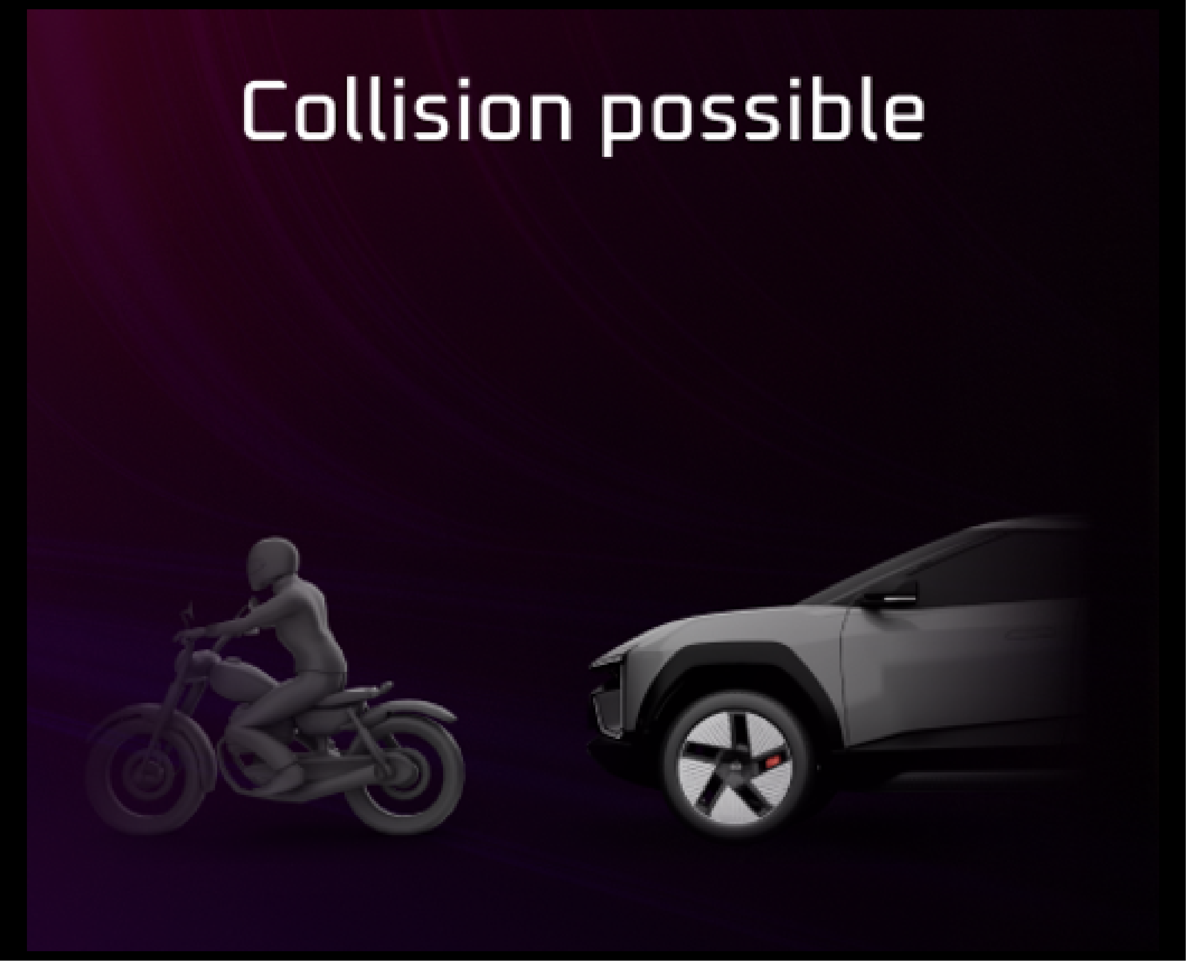
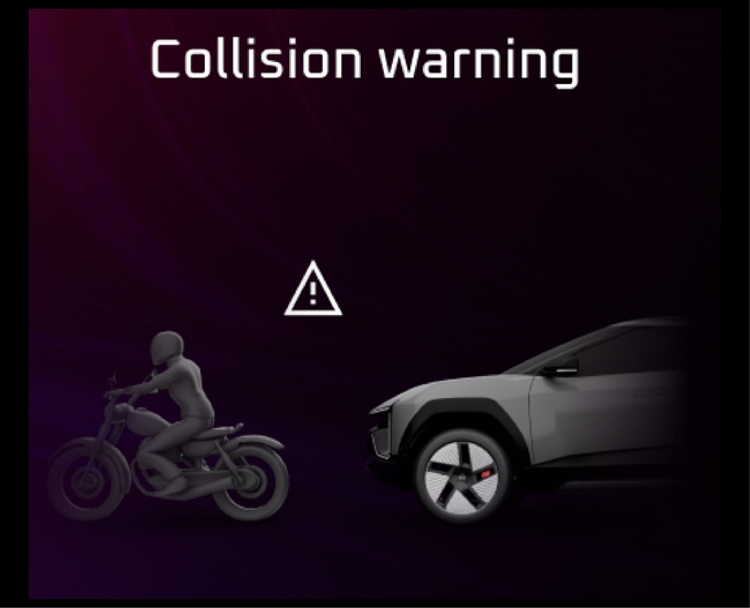
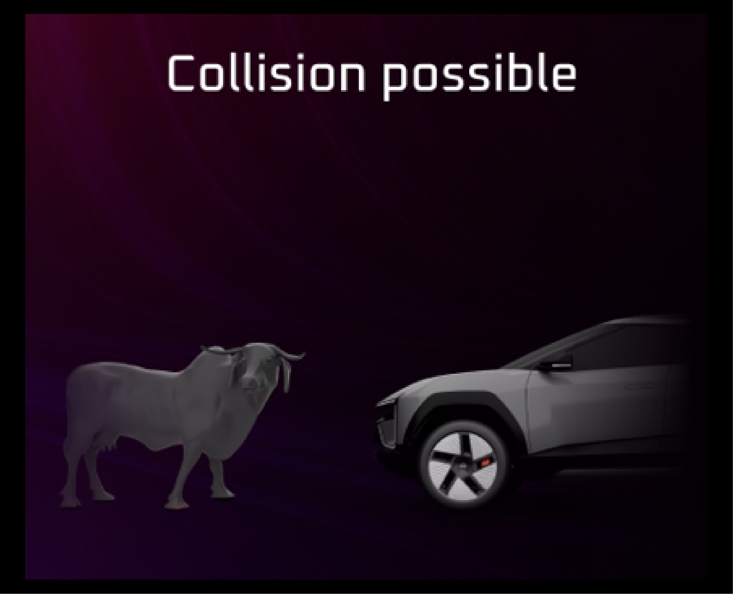
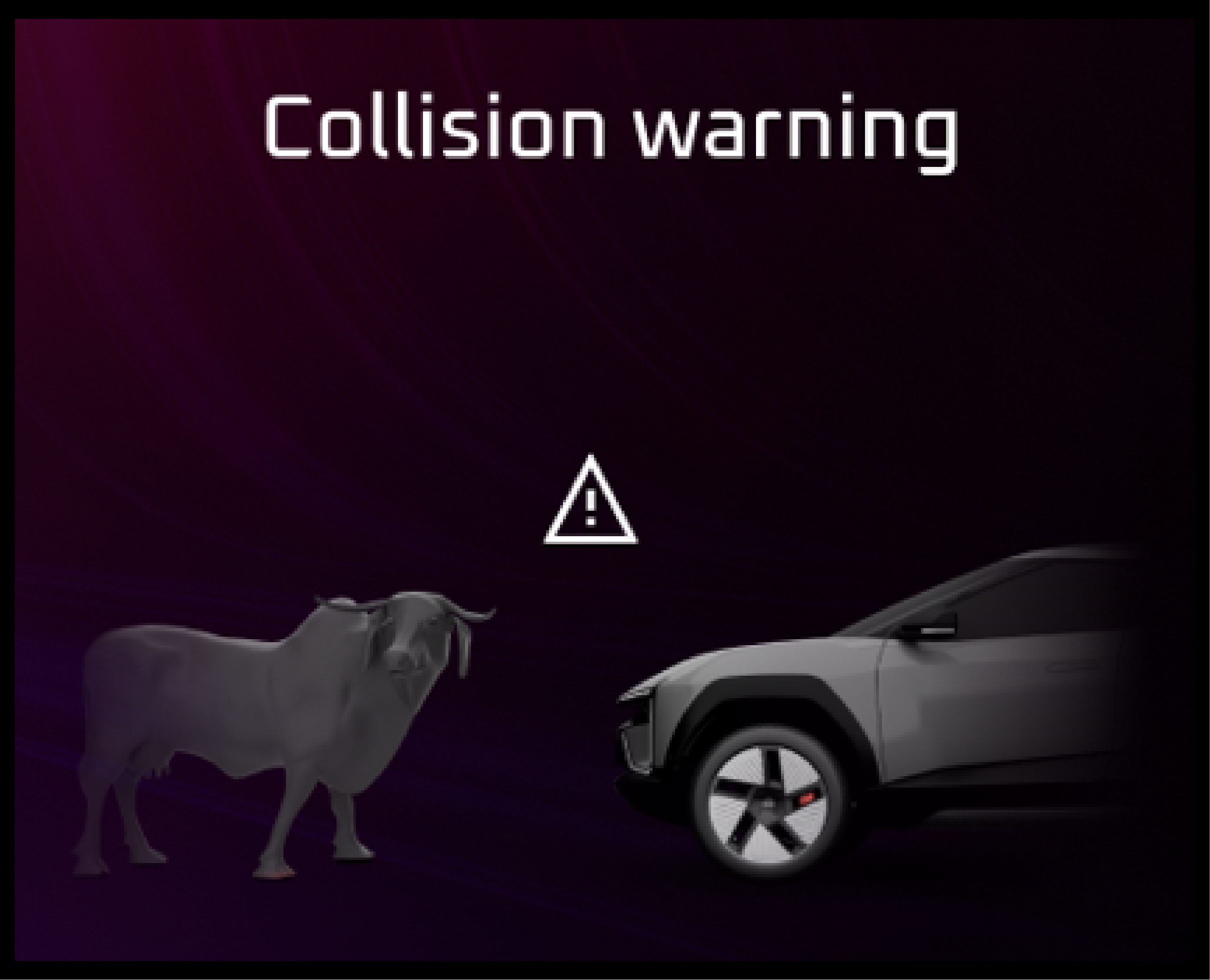
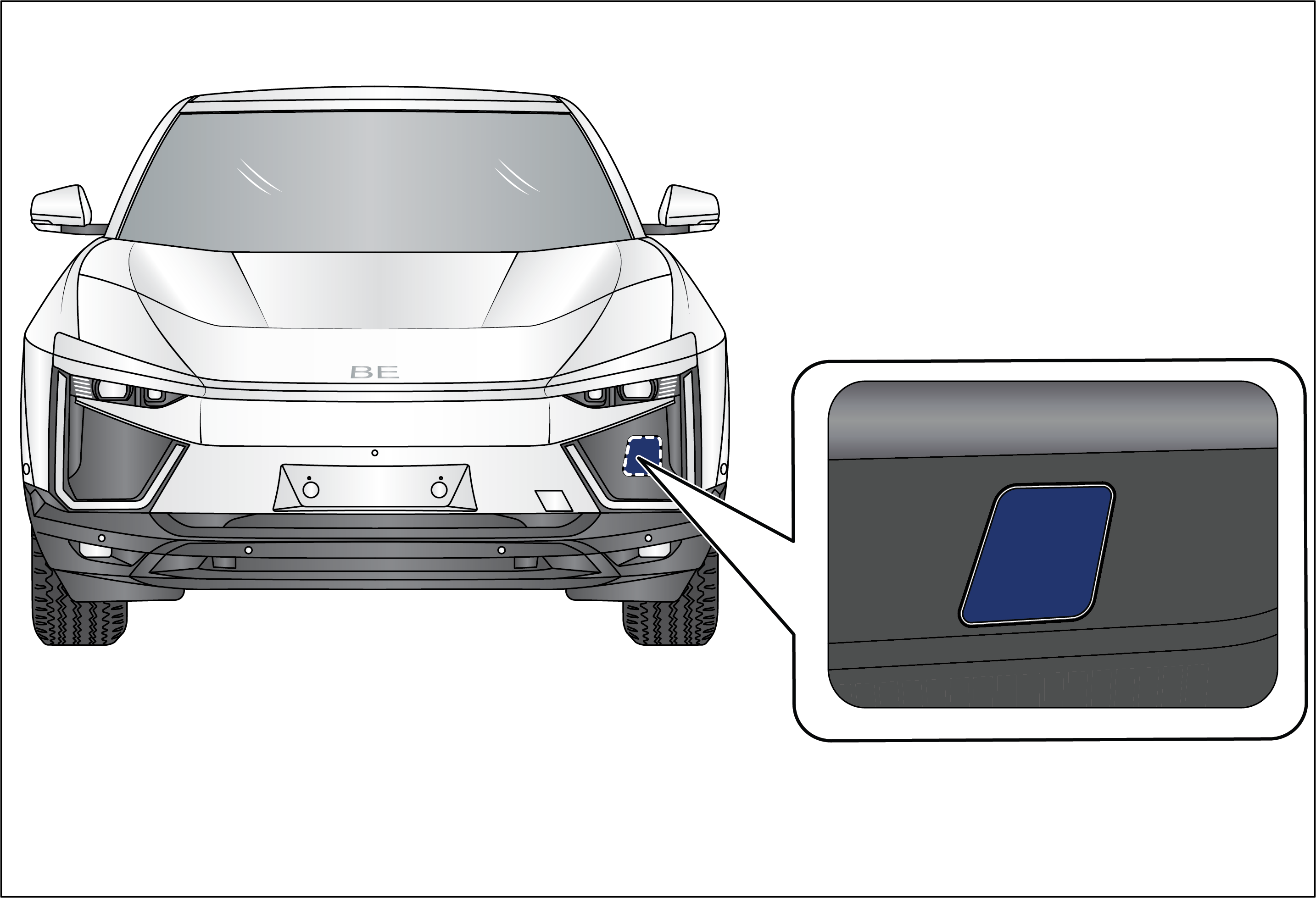
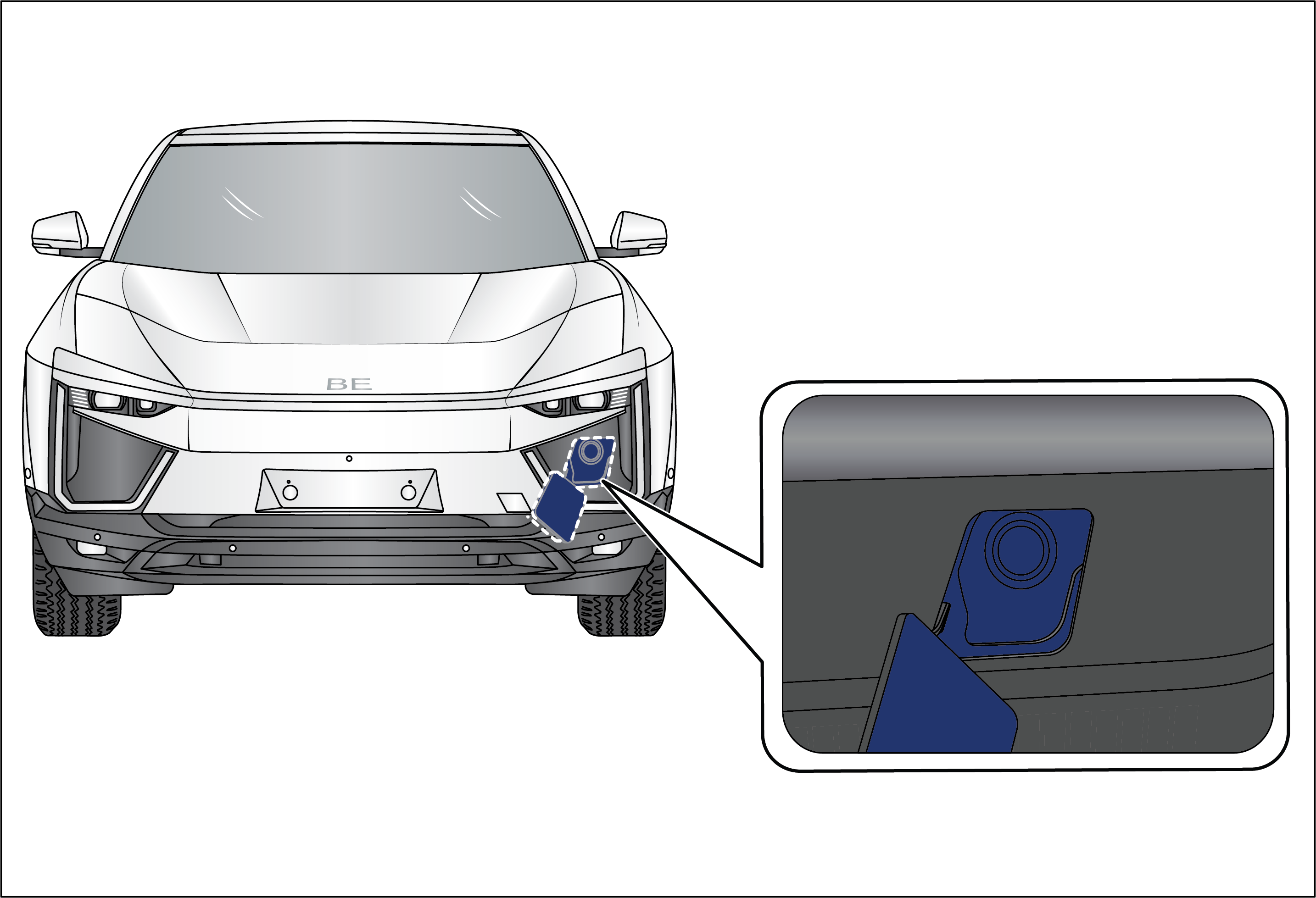
Autonomous Emergency Braking (AEB) |
Lamp on when ignition is turned on
Abnormal Operation:
Lamp continuously on indicates malfunction in the AEB system.
Actions recommended:
Check whether the front camera module is covered by any foreign particles. Clean using soft cloth if required. contact dealer
if lamp is still ON.
|
• |
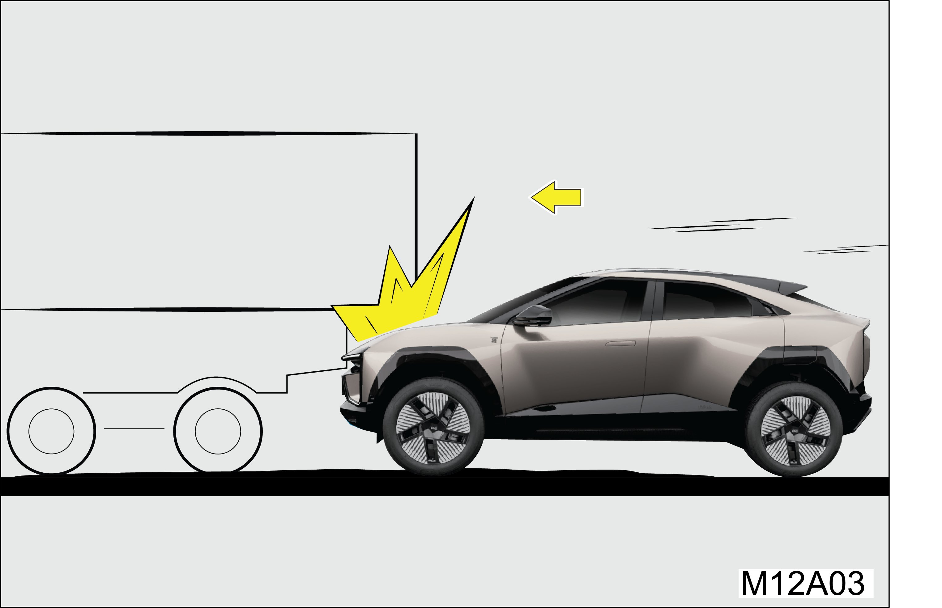
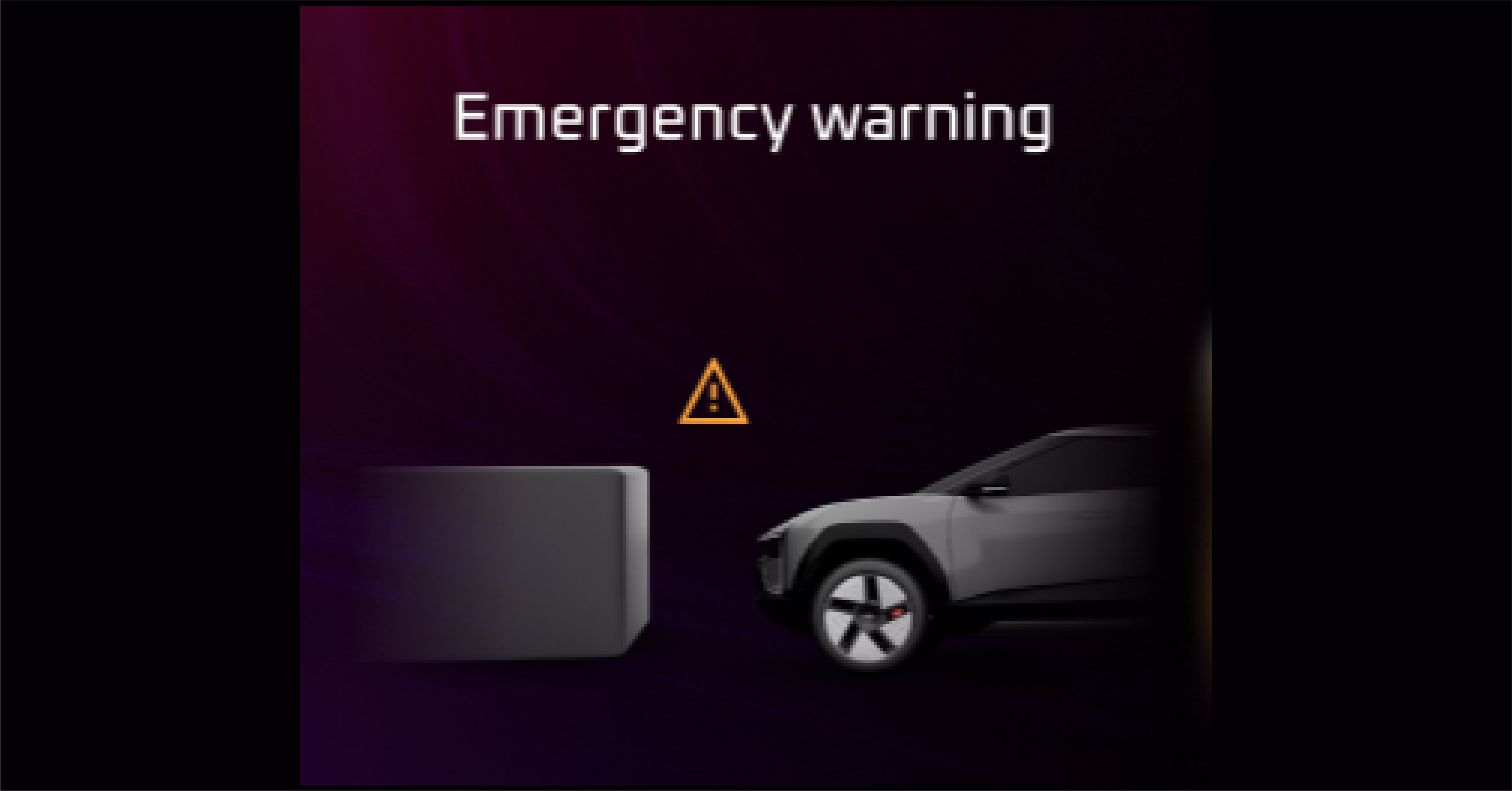
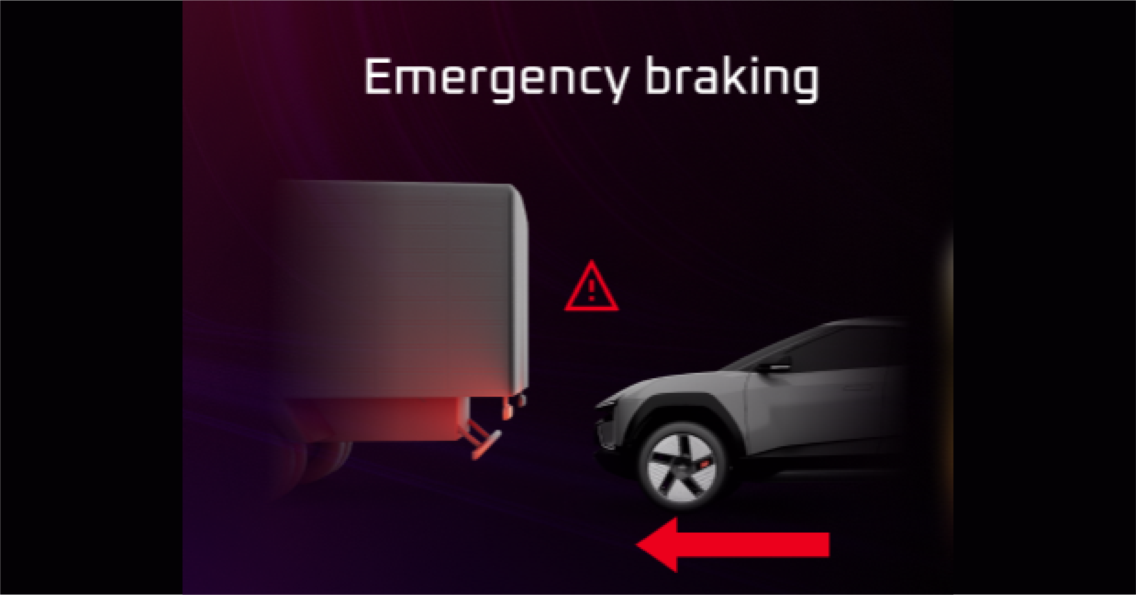
Advanced Emergency Braking System (AEBS) OFF |
It indicates the Vehicle running in AEBS OFF (Autonomous Emergency Braking system) condition
Abnormal Operation:
If the warning light remains ON when the AEB is activated, indicates malfunction in the system.
Actions recommended:
In case of any malfunction, immediately contact the nearest Mahindra authorised service centre
Lamp off during ignition is on. Lamp on when high beam is on in AUTO mode and high beam assist function is enabled in cluster.
Abnormal Operation:
Lamp not turning on/off when head lamp high beam is on/off in AUTO mode and high beam assist in enabled state indicates malfunction
in the system.
Actions recommended:
In case of any malfunction, immediately contact the nearest Mahindra authorised service centre
|
• |
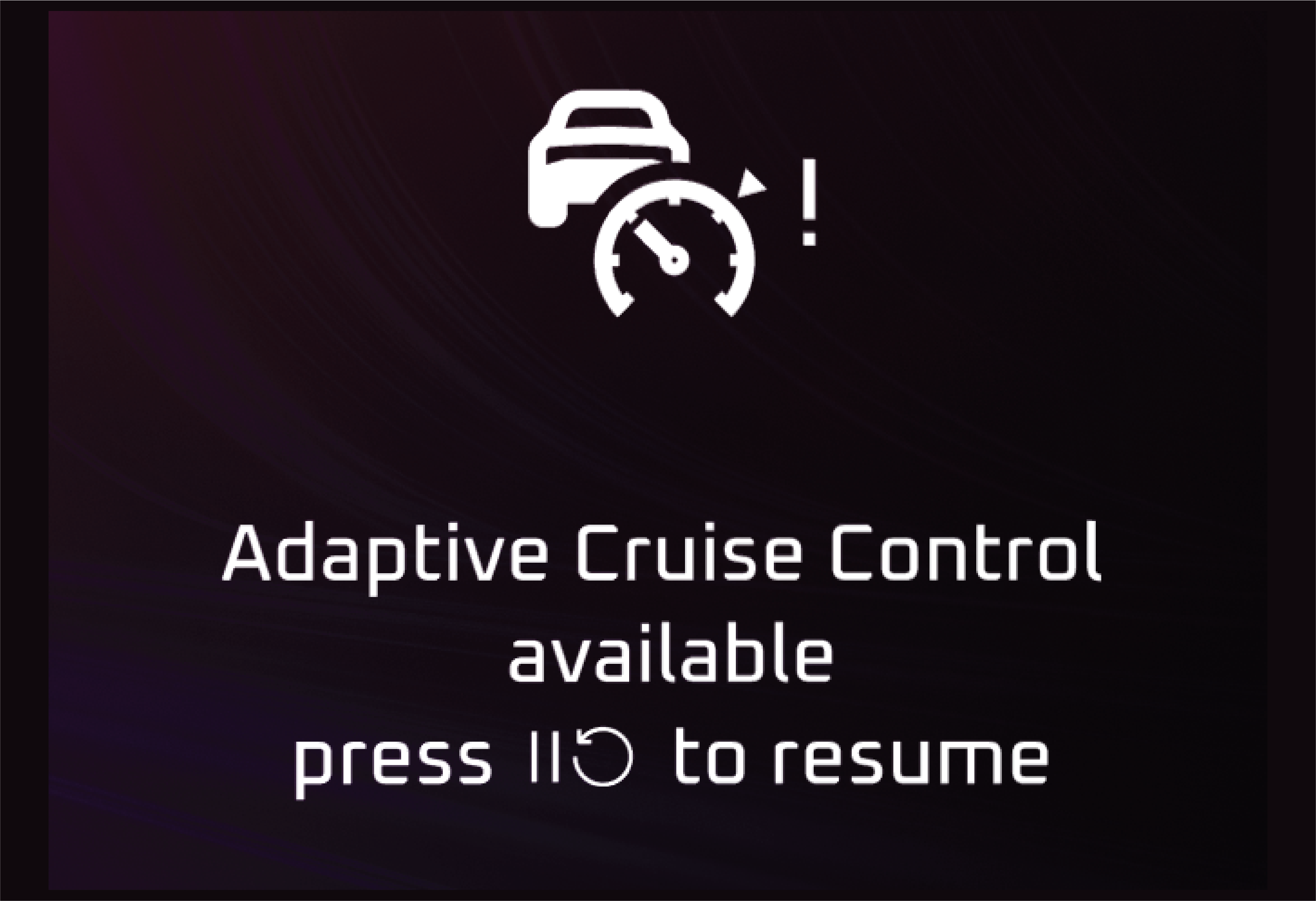
Adaptive Cruise Control White |
Lamp on when ACC function is enabled through steering wheel switches. ACC system indicates inactive state in white color.
|
• |
Adaptive Cruise Control Green |
Lamp on when ACC function is enabled through steering wheel switches. ACC system indicates Active state in green color.
|
• |
Adaptive Cruise Control Yellow |
Abnormal Operation:
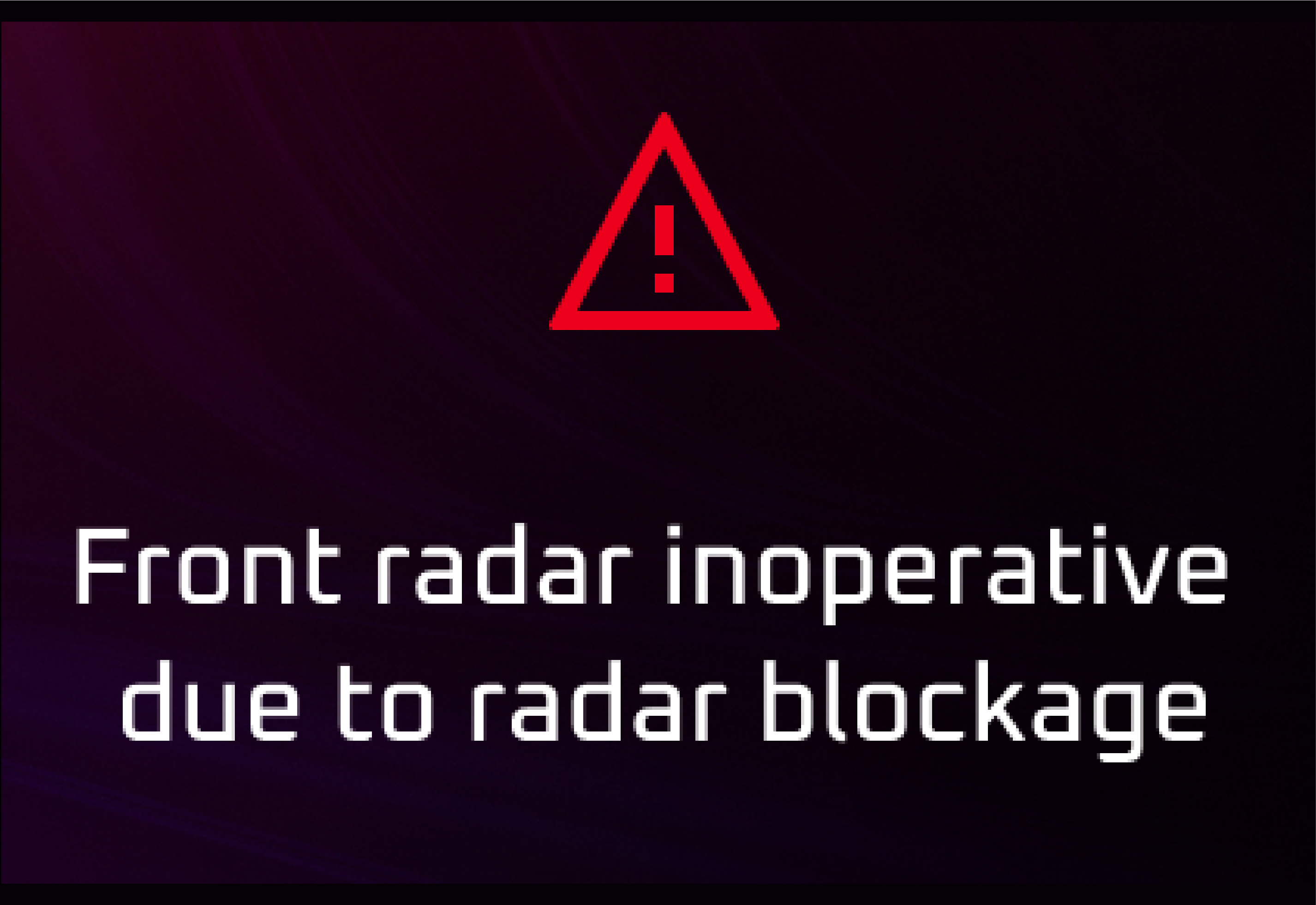
ACC system in yellow color indicates temporarily ACC not available due to abnormal condition
Actions recommended:
In yellow lane, check the front camera/front radar module is covered by any foreign particles and if required clean using
the soft cloth and still in yellow color contact Mahindra Authorised Service Center for assistance..
|
• |
Adaptive Cruise Control Red |
Abnormal Operation:
ACC system in red color indicates ACC Not Working/Fail State. Do not rely solely on Adaptive Cruise Control to operate your
vehicle. You remain responsible for maintaining safe control of the vehicle at all times.
Actions recommended:
In Red lane, check the front camera/front radar module is covered by any foreign particles and if required clean using the
soft cloth and still in red color contact Mahindra Authorised Service Center for assistance.
|
• |
Auto Vehicle Hold Yellow |
Abnormal Operation:
Yellow light Indicates some fault in AVH, because of which AVH not available.
Actions recommended:
For yellow light on contact an Mahindra Authorised Service Center.
|
• |
Auto Vehicle Hold White |
White colour: Lamp on when AVH is enabled through AUTO HOLD switch in centre console. AVH is available in white color indicates
standby mode.
|
• |
Auto Vehicle Hold Green |
Green colour: Lamp on when SPA is enabled through AUTO HOLD switch in centre console. AVH is available in green color indicates
Active mode. Lamp blinks in green indicates steering assistance is provided to maintain the vehicle in center of the lanes.
Abnormal Operation:
Auto Hold system in red color indicates Auto Hold Not Working/Fail State.
Actions recommended:
For red light on contact an Mahindra Authorised Service Center.
|
• |
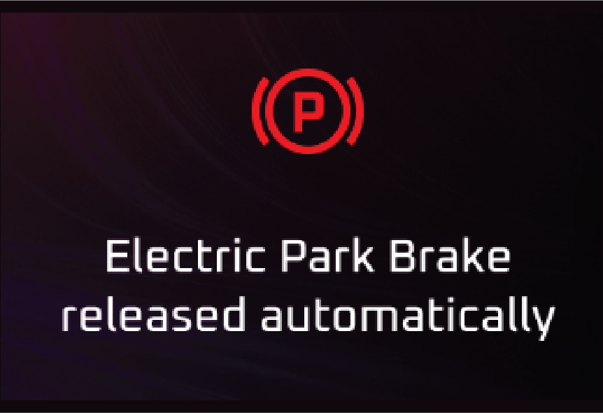
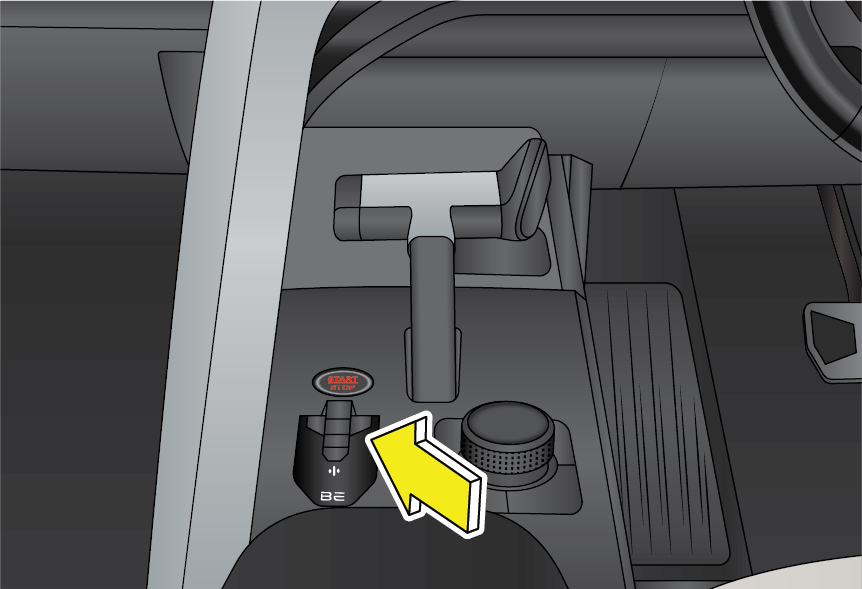
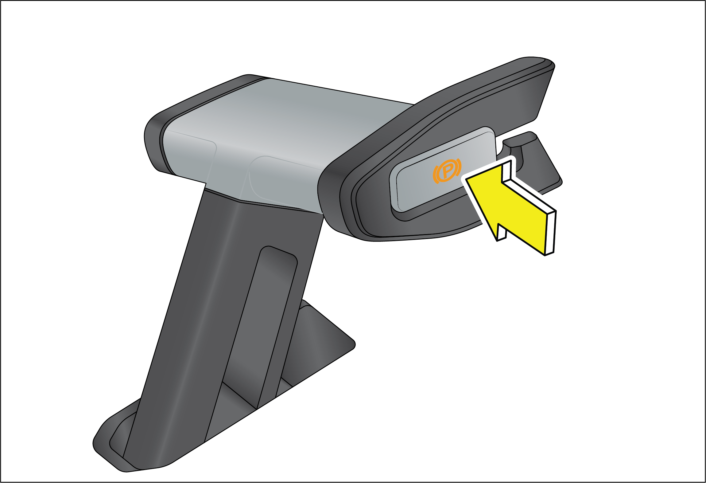
Electronic Parking Brake (EPB) |
Lamp on when ignition is turned on and goes off in few seconds.
Abnormal Operation:
Lamp continuously on indicates malfunction in EPB system.
Actions recommended:
EPB doesn't work Contact the authorized dealer immediately for assistance.
EV warning tell tale is used to indicate all system level/component level EPT faults.
Abnormal Operation:
Lamp continuously on indicates malfunction in EPT system.
Actions recommended:
Contact your nearest Authorized Mahindra Service Center immediately.
|
• |
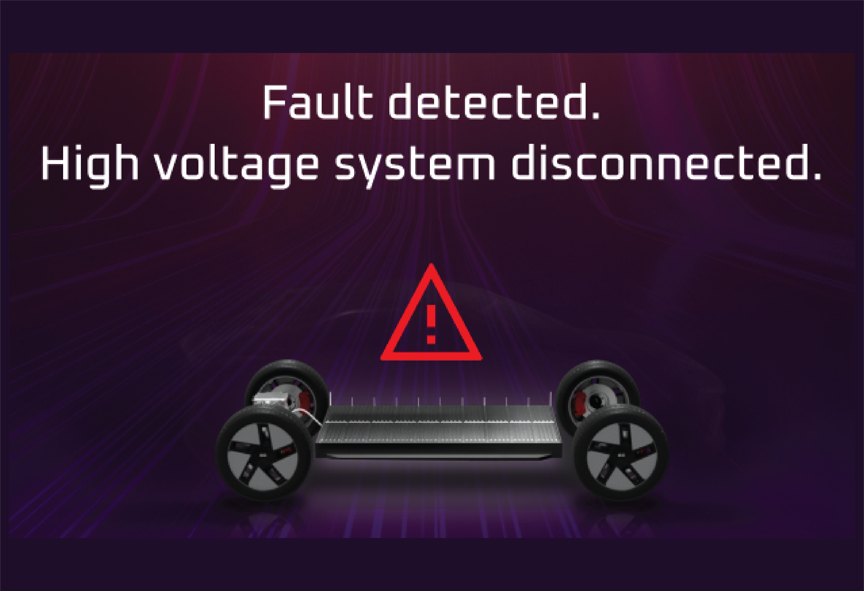
HV (High Voltage) Battery Failure |
Abnormal Operation:
If it is continuously ON indicates that HV Battery Fail.
|
• |
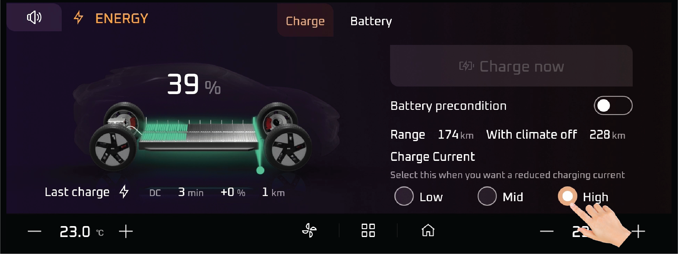
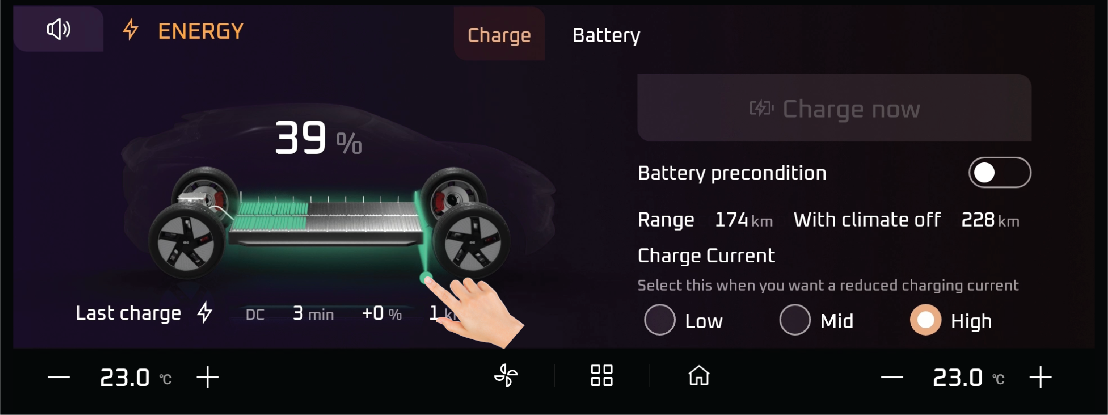
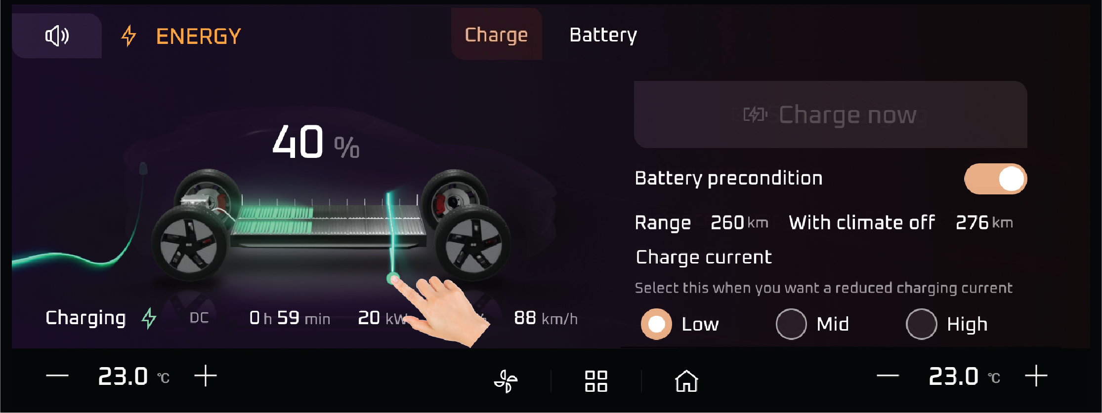
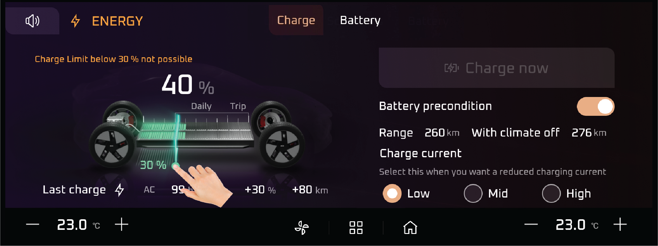
HV (High Voltage) Battery Charge Lamp |
If it is Continuously ON Indicates that HV battery charging is in progress.
Abnormal Operation:
Lamp is still ON when Vehicle is not in charging .
Actions recommended:
HV Battery Charge Lamp doesn’t work Contact Mahindra Authorised Service Center for Assistance
If it is continuously ON it Indicates that vehicle is in regeneration state due to braking regeneration/coasting regeneration.
Abnormal Operation:
If it is in ON though braking is not happening
Actions recommended:
Regeneration Lamp doesn't work Contact the authorized dealer immediately for assistance.
If lamp is not ON even though braking then please contact Mahindra Authorised Service Center for Assistance
When the vehicle Ignition is turned ON & drive is enabled, after successful security authentication. This lamp illuminates
indicating user that the vehicle is ready to drive.
Actions recommended:
While Vehicle is moving it is not shown then Contact Mahindra Authorised Service Center for Assistance
|
• |
Electronic Parking Brake (EPB) malfunction |
Lamp on when ignition is turned on and goes off in few seconds.
Abnormal Operation:
Lamp continuously on indicates malfunction in EPB system.
Actions recommended:
Indicates malfunction of Electric Parking Brake. Contact a Mahindra Authorised Service Center immediately.
Indicates vehicle need to go for an Service
Abnormal Operation:
If it is Continuously ON then Indicates that there is a fault related to Non-EPT components.
Actions recommended:
Contact Mahindra Authorised Service Center for assistance
|
• |
Lane Follow Assist Yellow |
Abnormal Operation:
Yellow lamp on/blinks indicates the malfunction in the system and LFA function may not be available.
Actions recommended:
In yellow lane, check the front camera module is covered by any foreign particles and if required clean using the soft cloth
and still in yellow color contact dealer.
|
• |
Lane Follow Assist White |
Lamp turns on when LFA fuction is enabled through cluster. lamp remains on in white color represents the system in the stand
by mode
|
• |
Lane Follow Assist Green |
Lamp turns on when LFA function is enabled through cluster. Lamp remains on in green color represents the system in the Active
mode. lamp blinks in green colour when steering assistance is provided to avoid the lane follow.
|
• |
Lane Depature Warning Yellow |
Abnormal Operation:
Yellow lamp on/blinks indicates the malfunction in the system and LDW function may not be available.
Actions recommended:
In yellow lane, check the front camera module is covered by any foreign particles and if required clean using the soft cloth
and still in yellow color contact dealer.
|
• |
Lane Depature Warning White |
Lamp turns on when LDW function is enabled through cluster. Lamp remains on in white color represents the LDW system in the
stand by mode.
|
• |
Lane Depature Warning Green |
Lamp turns on when LDW fuction is enabled through cluster. lamp remains on in green color represents the system in the Active
mode. lamp blinks in green colour indicates lane departure is detected by LDW system
|
• |
Lane Keep Assist Yellow |
Abnormal Operation:
Yellow lamp on/blinks indicates the malfunction in the system and LKA function may not be available.
Actions recommended:
In yellow lane, check the front camera module is covered by any foreign particles and if required clean using the soft cloth
and still in yellow color contact dealer.
Lamp turns on when LKA function is enabled through cluster. Lamp remains on in white color represents the system in the stand
by mode.
Lamp turns on when LKA function is enabled through cluster. Lamp remains on in green color represents the system in the Active
mode. lamp blinks in green colour when steering assistance is provided to avoid the lane departure.
The temperature warning lamp indicates the high & low temperature condition of EPT components which may lead to malfunction
of EPT components Blinking indicates extreme temperature condition & continuous ON indicates very extreme temperature condition.
Abnormal Operation:
Blinking indicates extreme temperature condition & continuous ON indicates very extreme temperature condition
Actions recommended:
Do not continue driving the vehicle with this lamp ON. This may result in damage to the components and will not be covered
under warranty. The user must immediately visit the nearest Mahindra authorised service centre.
|
• |
HDC (Hill Descent Control) Malfunction Telltale |
The lamp comes on when the ignition switch is turned ON and goes off after about 4 seconds.
Abnormal Operation:
If Lamp Continuous ON malfunction warning lamp indicates malfunction in HDC system.
Actions recommended:
Contact the nearest Mahindra Authorized Dealer.
|
• |
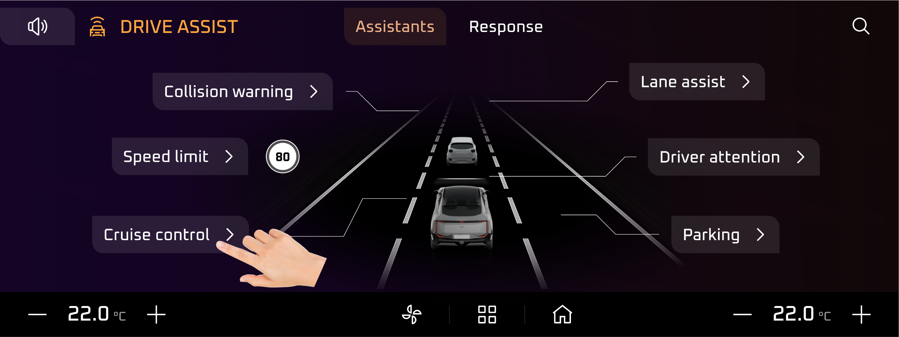
Cruise Control Indicator |
The white cruise control indicator illuminates on the dashboard when the cruise control system is in standby mode, meaning
it is ready to be activated but not currently maintaining a set speed. It indicates that the system is operational and can
be engaged by the driver.
Actions recommended:
Always be prepared to disengage the cruise control system by pressing the brake pedal, clutch (for manual transmission), or
the cancel button in challenging driving conditions. If the white indicator does not turn on or behave as expected, consult
an authorized service center to check the cruise control system.
|
• |
Cruise Control Indicator Green |
The green cruise control indicator illuminates on the dashboard when the cruise control system is actively maintaining the
set speed of the vehicle. It signifies that the system is engaged and operational.
Actions recommended:
If the tell-tale flashes or remains illuminated after turning off cruise control, consult an authorized service center to
diagnose and resolve potential issues.
|
• |
Cruise Control Indicator Yellow |
The yellow cruise control indicator illuminates when there is an issue or limitation with the cruise control system, rendering
it unavailable or partially functional. It serves as a warning that the system requires attention before it can be safely
used.
Actions recommended:
Schedule a check-up with an authorized service technician to diagnose and resolve the issue causing the yellow indicator.
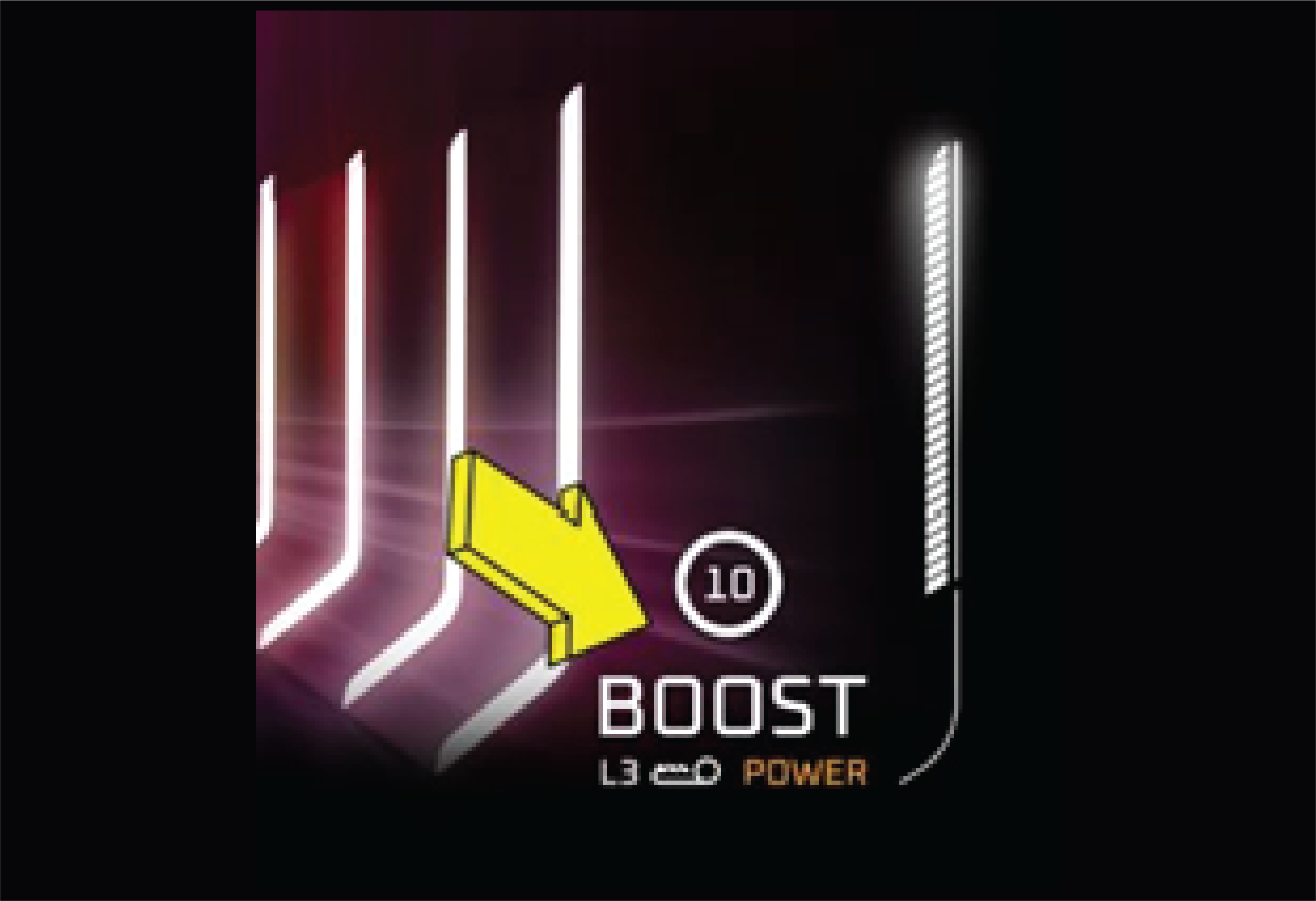
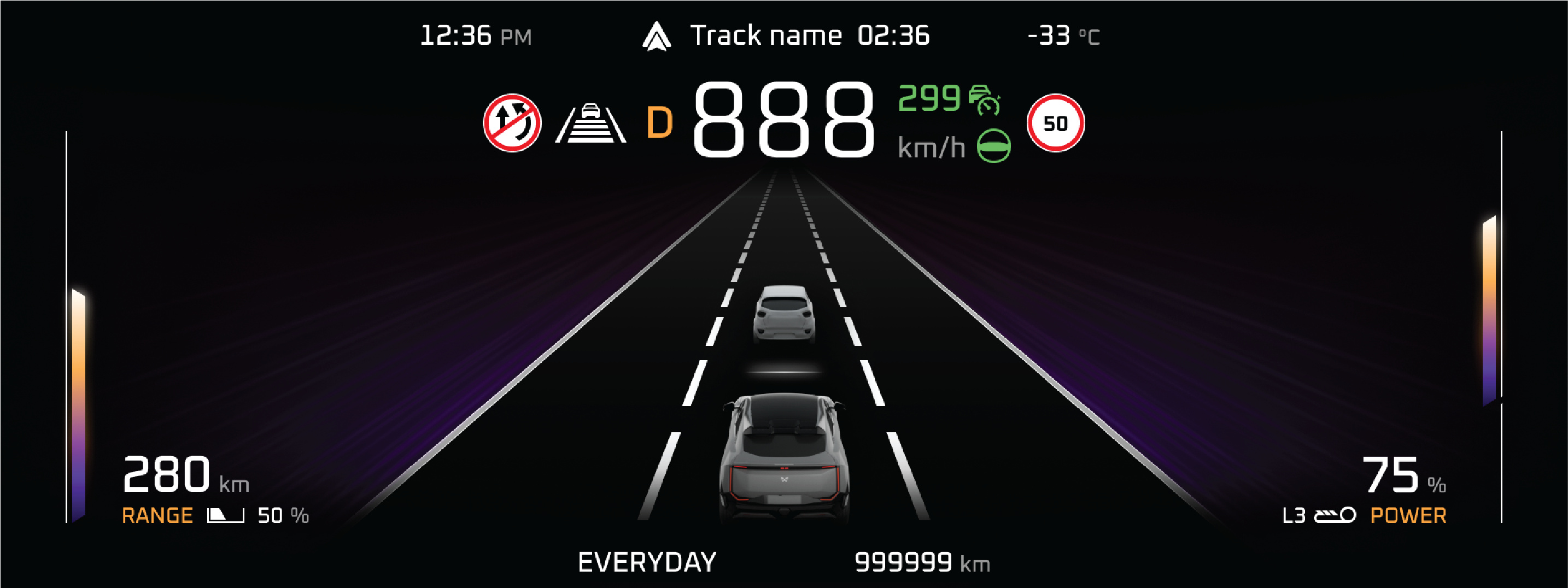
The ACC (Adaptive Cruise Control) Distance Lane 3 tell-tale indicates that the longest following distance is selected for
the adaptive cruise control system. It represents the highest level of gap setting, ensuring the maximum distance between
your vehicle and the vehicle ahead.
Actions recommended:
If conditions improve or traffic becomes lighter, you may consider reducing the following distance by adjusting the ACC settings
to a shorter gap (Lane 1 or Lane 2) for smoother traffic flow.
The ACC (Adaptive Cruise Control) Distance Lane 2 tell-tale indicates that a medium following distance is selected for the
adaptive cruise control system. This setting balances safety and efficiency, maintaining a moderate gap between your vehicle
and the vehicle ahead.
Actions recommended:
For adverse weather, heavy traffic, or high speeds, consider increasing the following distance to Lane 3 for enhanced safety.
In lighter traffic, you may reduce the distance to Lane 1 for improved traffic efficiency.
The ACC (Adaptive Cruise Control) Distance Lane 1 tell-tale indicates that the shortest following distance has been selected
for the adaptive cruise control system. This setting minimizes the gap between your vehicle and the vehicle ahead, prioritizing
efficiency in light traffic conditions.
Actions recommended:
If driving conditions worsen or traffic becomes heavier, increase the following distance to Lane 2 or Lane 3 for improved
safety margins.
|
• |
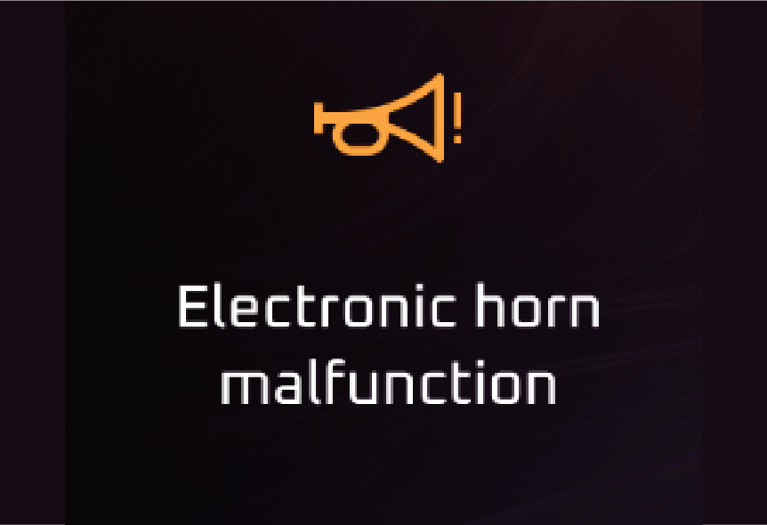
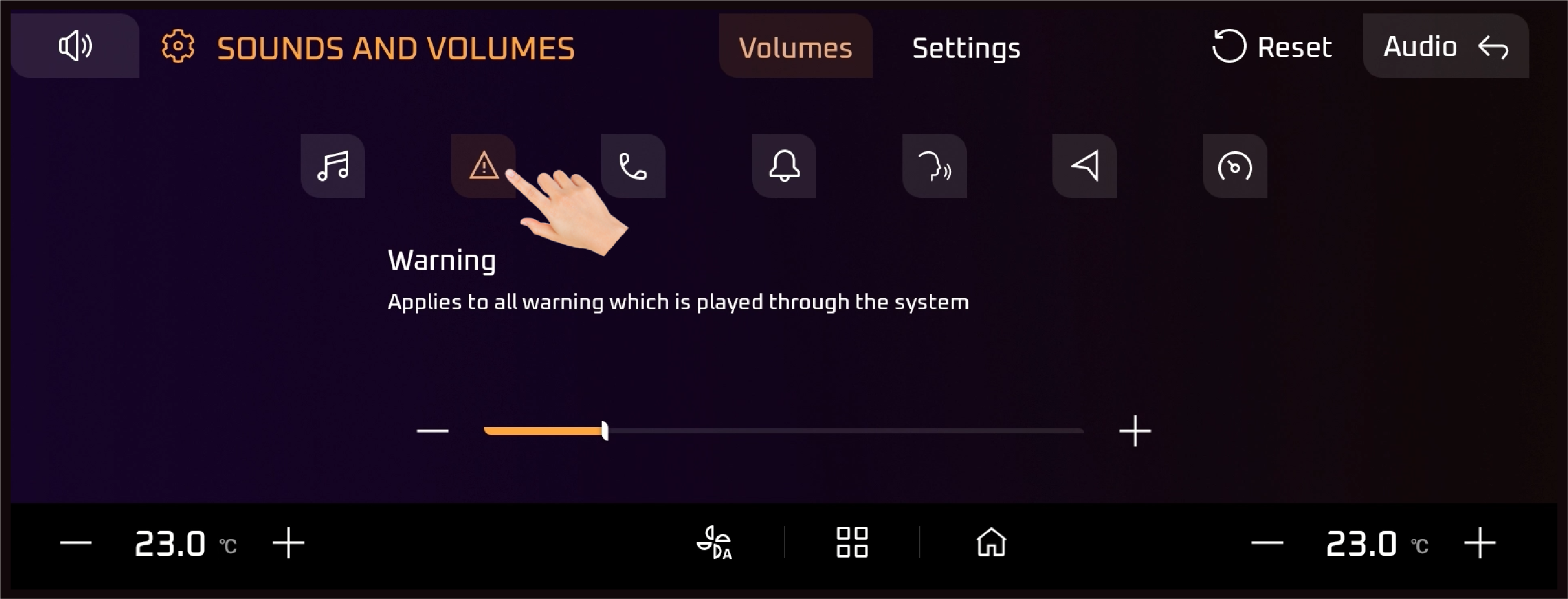
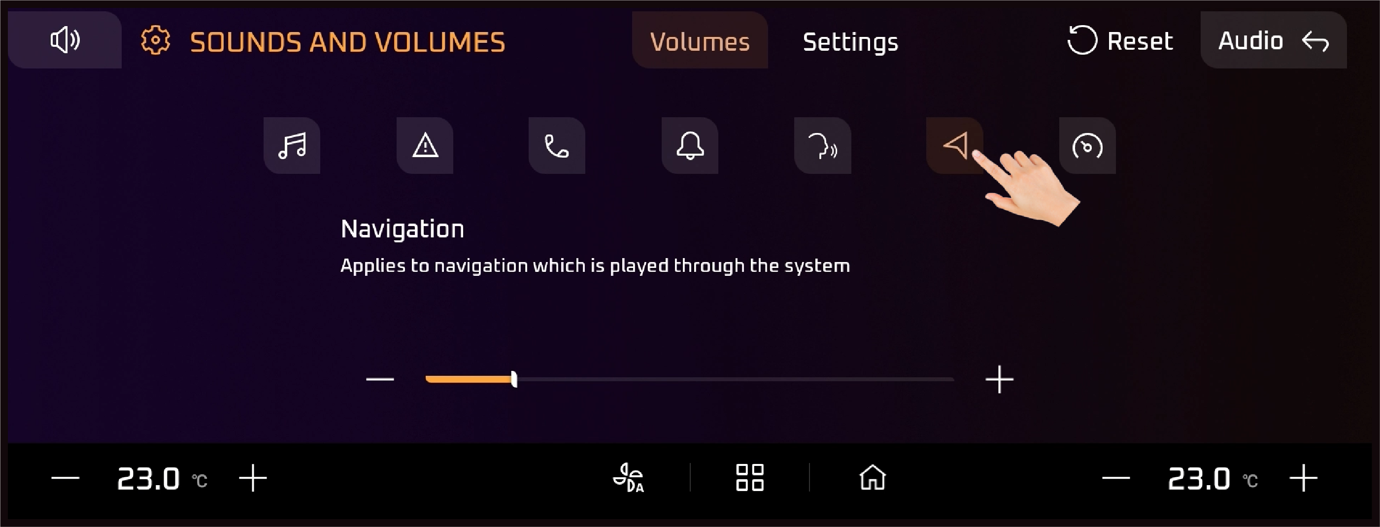
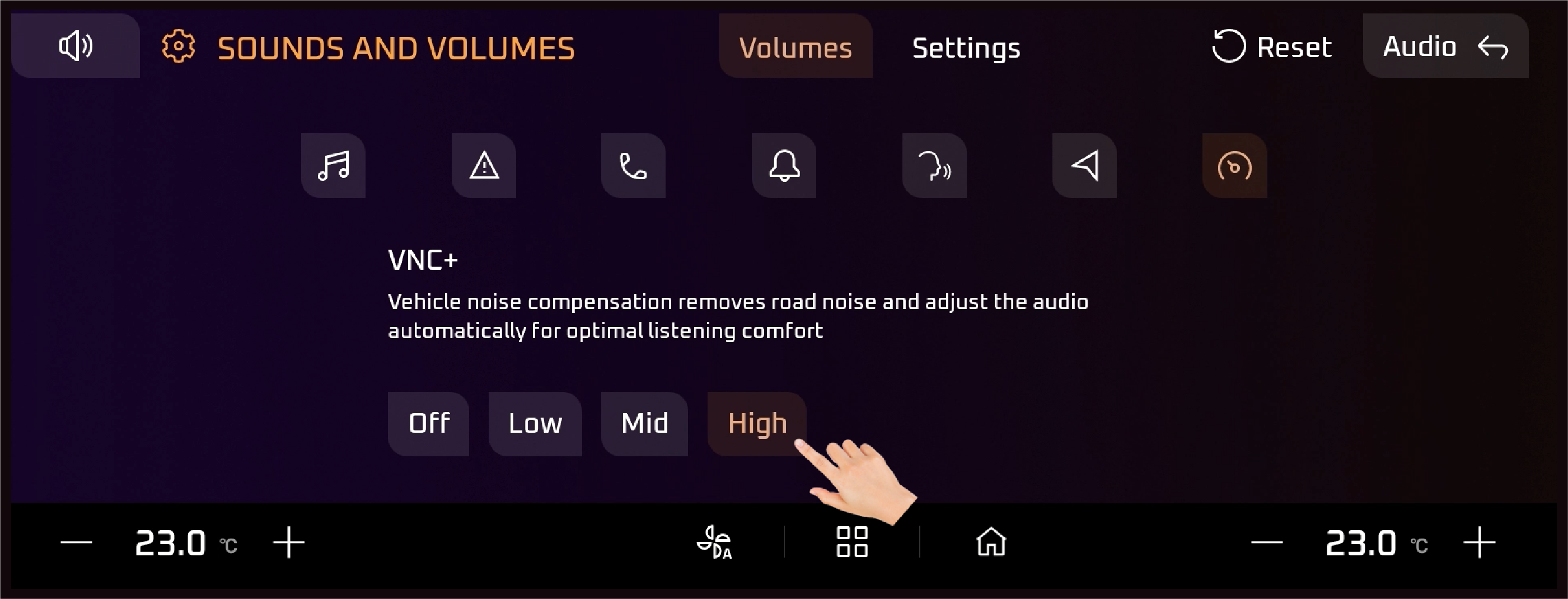
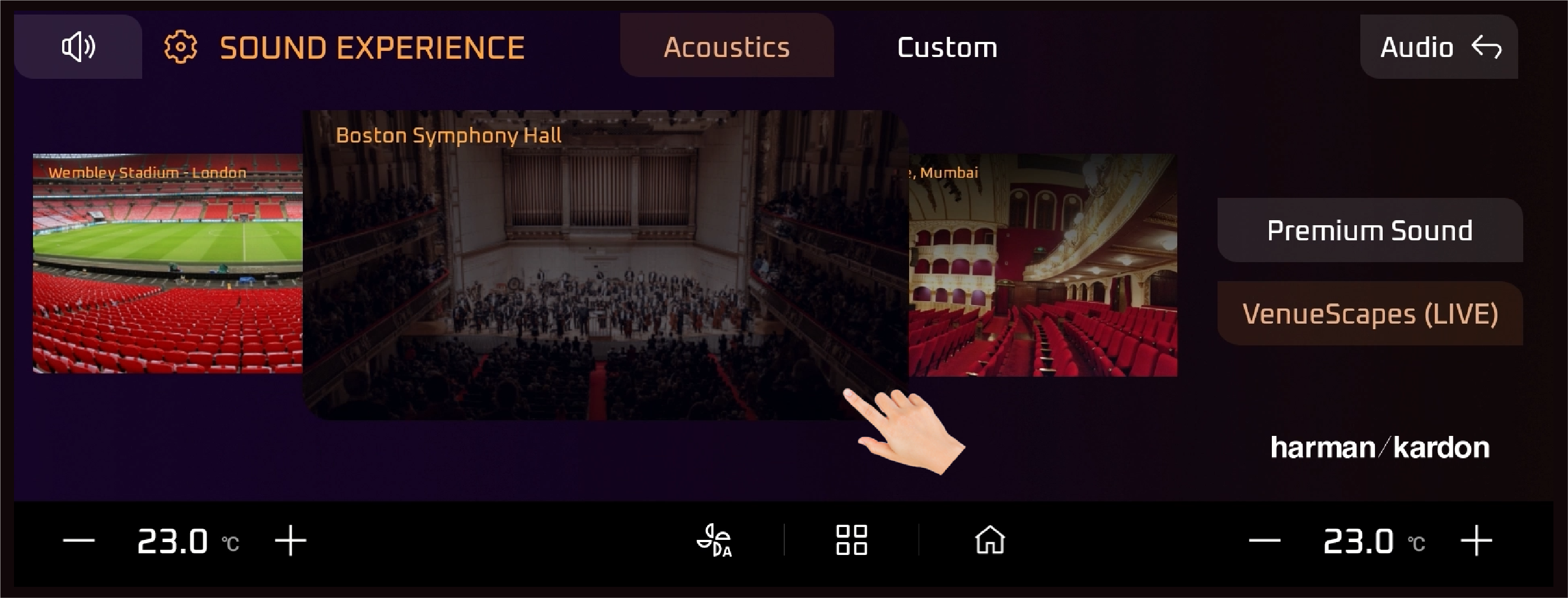
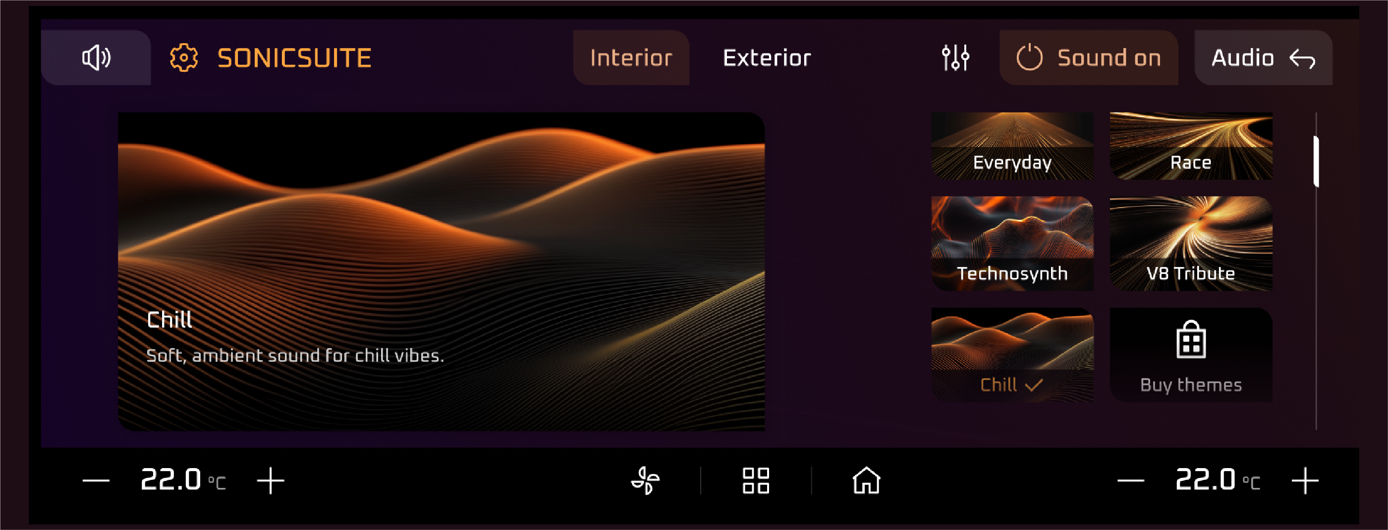
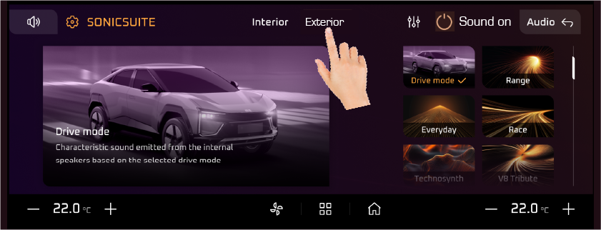
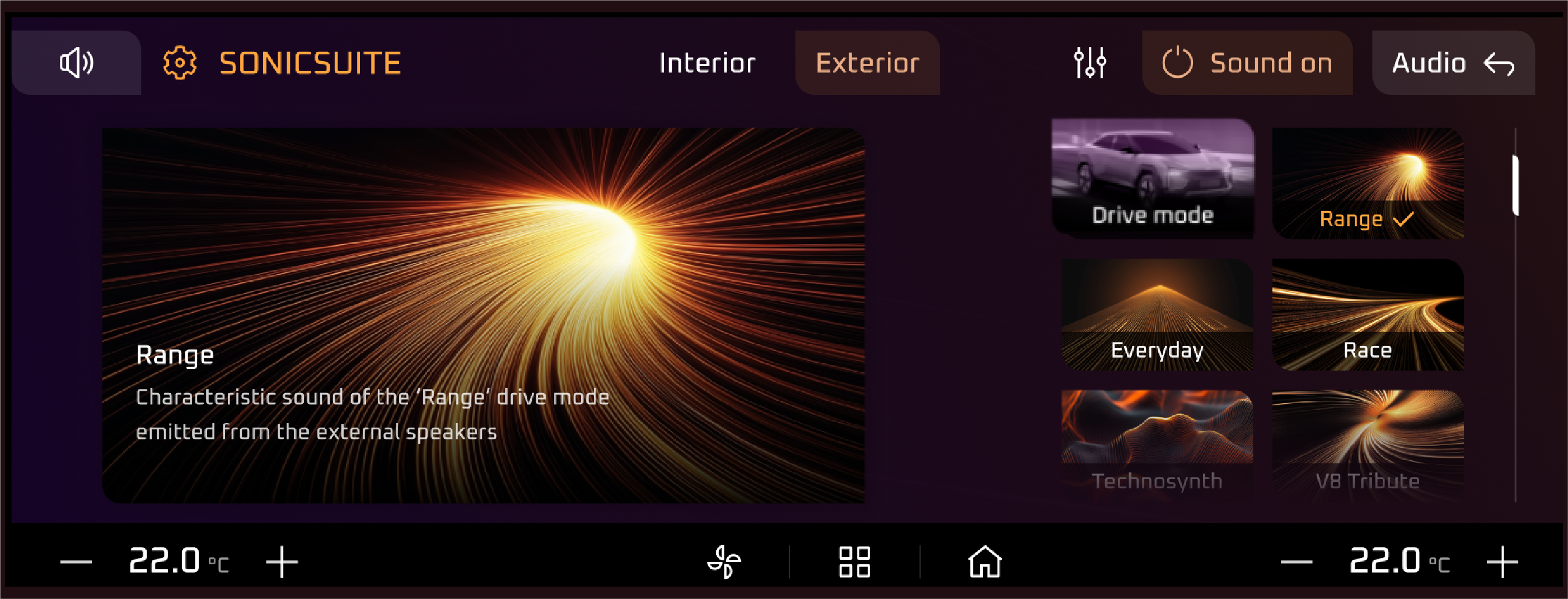
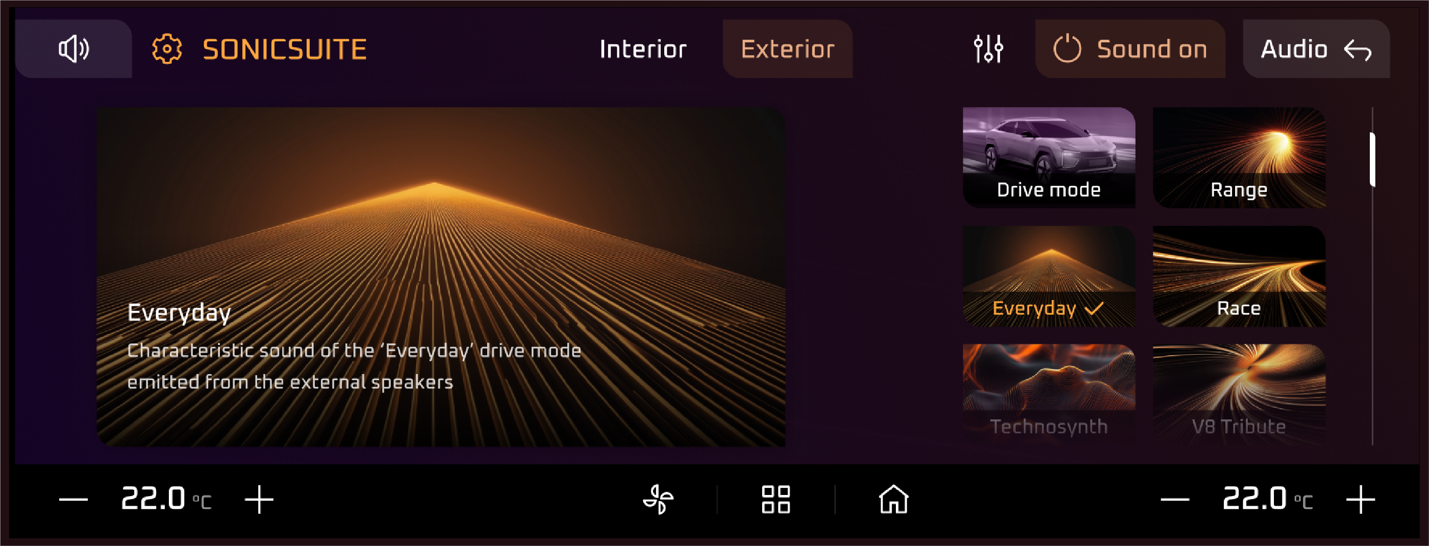
Virtual Sound Programme (VSP) |
The VSP tell-tale illuminates when there is a fault in the sound system.
Actions recommended:
In case of any malfunction, immediately contact the nearest Mahindra authorised service centre.
The "Press Brake" tell-tale illuminates as a prompt to depress the brake pedal. This is typically required in specific scenarios,
such as: Starting the Vehicle: In vehicles with automatic transmissions or push-button start systems. Shifting Gears: To
move the gear selector from "Park" or "Neutral".
Actions recommended:
Firmly press and hold the brake pedal when the tell-tale illuminates. If the light remains on despite following the prompts,
consult the Vehicle's Manual or contact a Mahindra authorised service centre for assistance.
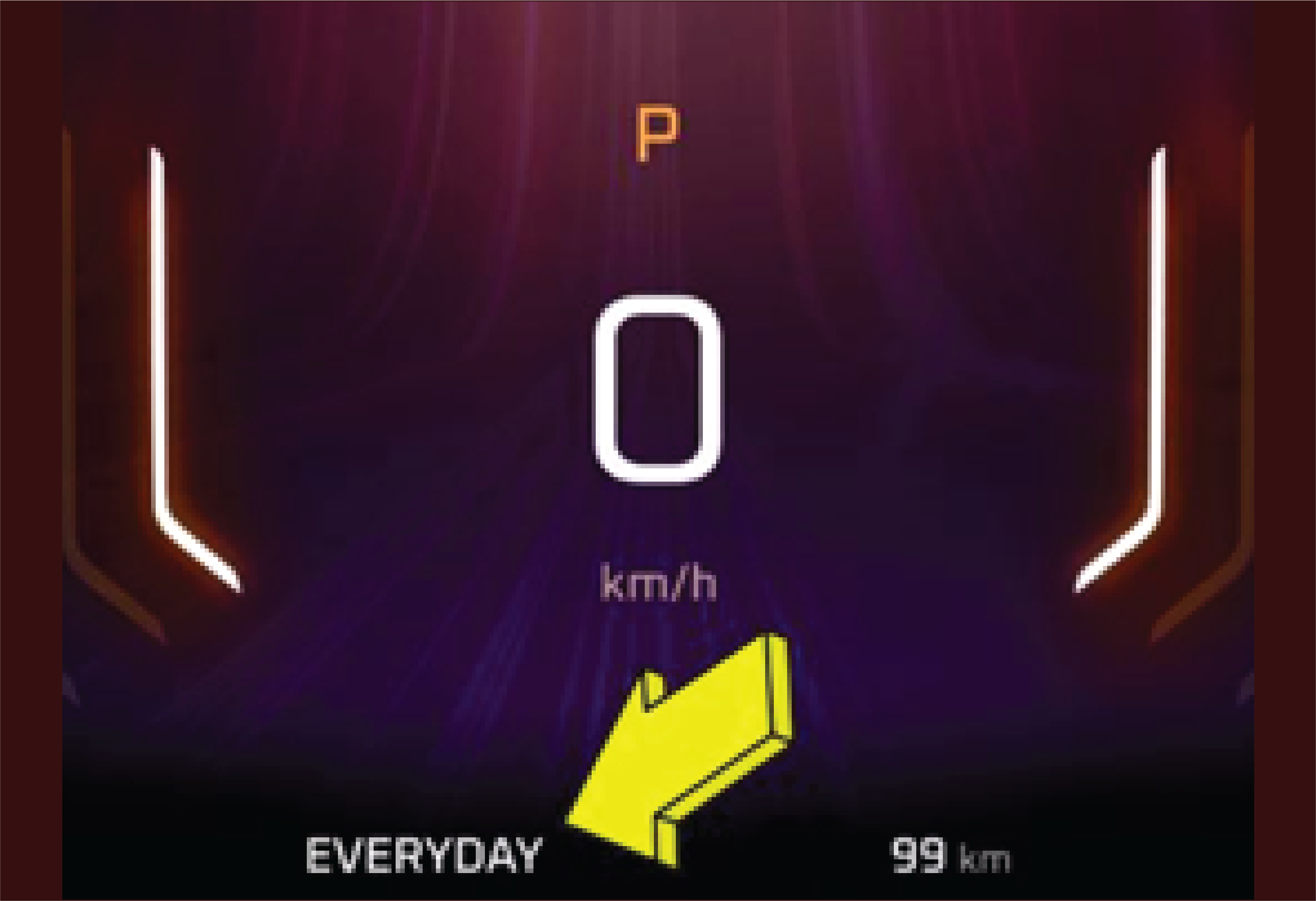
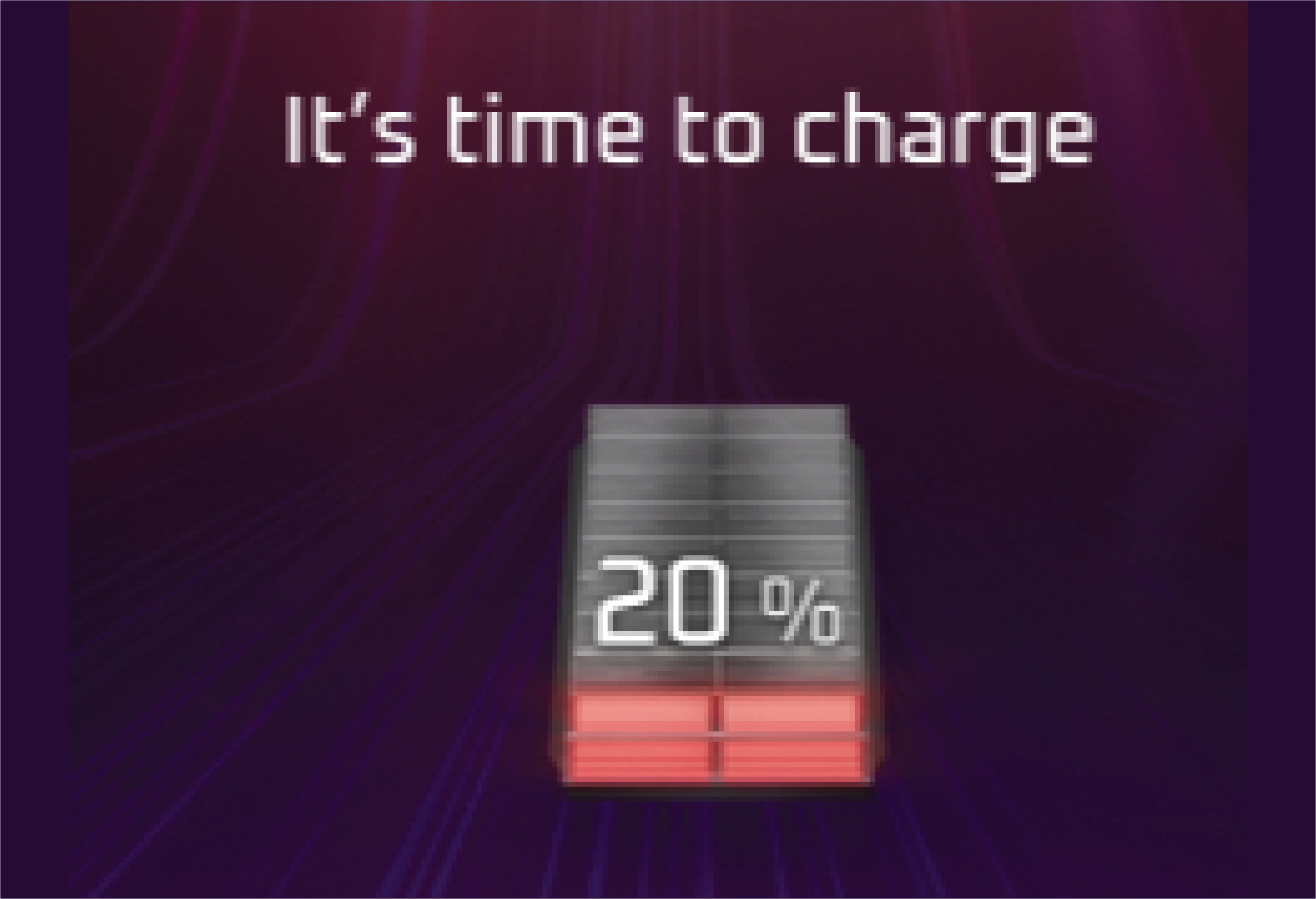
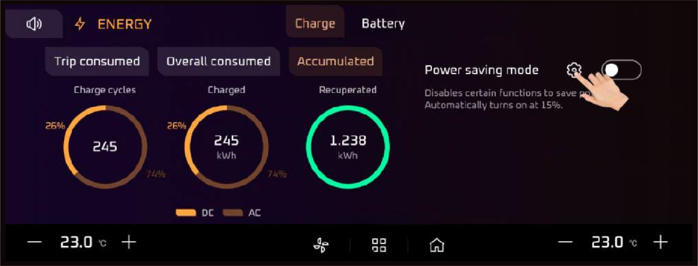
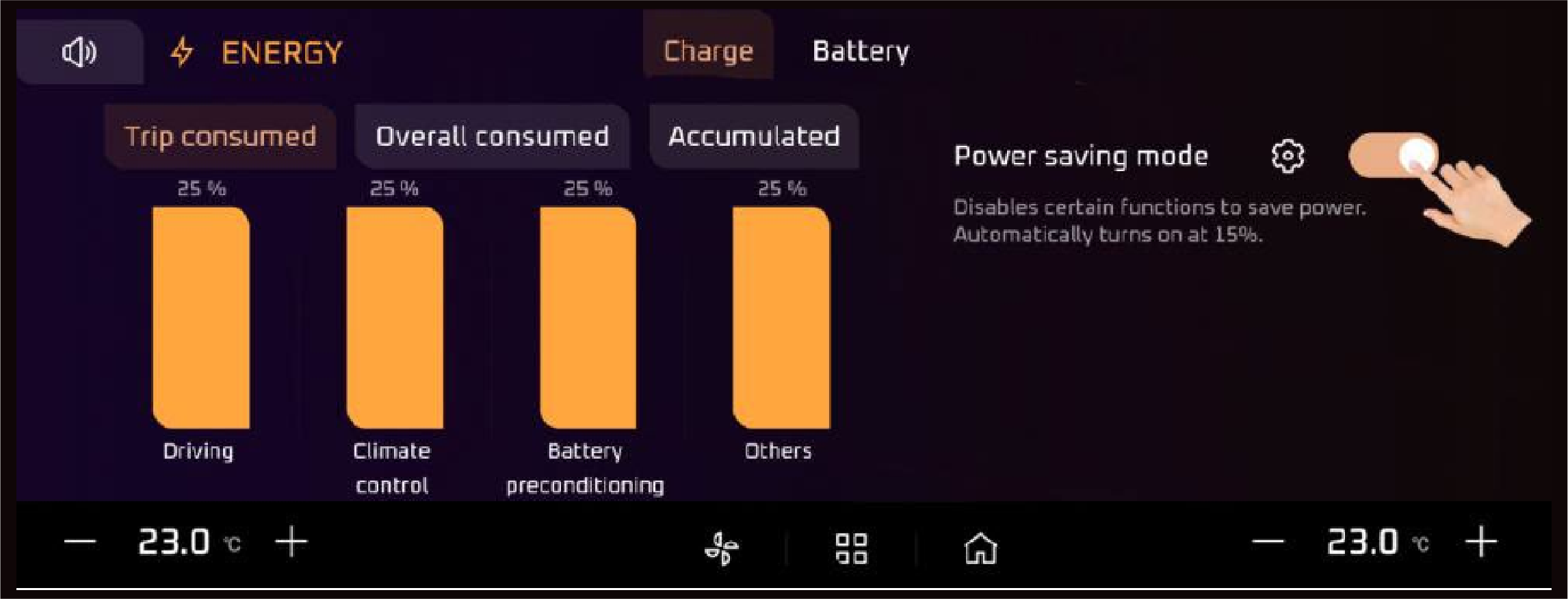
When the battery charge is critically low, the system enters Reduced Power Mode to conserve energy and prolong the vehicle's
range. A reduced power telltale will be displayed on the cluster to notify the driver that power output is limited to extend
the remaining range. When the vehicle reaches a very low SOC (State of Charge), the Limp Home Mode will activate. This mode
allows the vehicle to operate at minimal power, just enough to reach a nearby charging station.
Actions recommended:
If the SOC is greater than 20% and the tell tale appears then contact nearest dealer.
|
• |
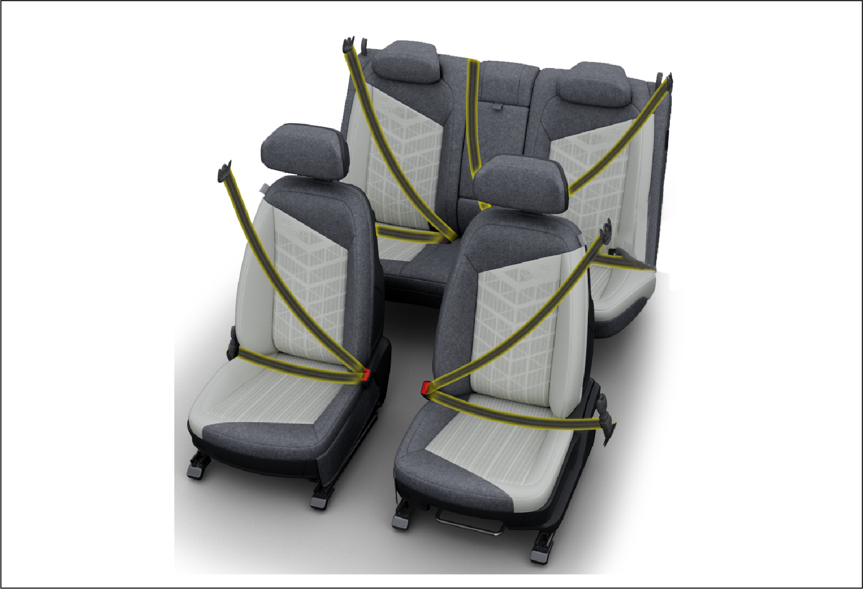
Rear Seat Belt Warning Lamp |
The Rear seat belt warning lamp illuminates and the buzzer chimes reminding the any one of the Passenger (if occupied) to
fasten the seat belt when the ignition is ON. The lamp will continue to illuminate till all the Passengers (if occupied) fastens
the seat belt properly.
Abnormal Operation:
If the passenger is not present or fastened the seat belt and lamp is present indicates malfunction in system
Actions recommended:
Contact the nearest Mahindra authorised service centre for assistance.
|
• |
Traffic Sign Recognition (TSR) |
|
Pedestrian Crossing
|
|
Give Way
|
|
|
Speed bump ahead
|
|
Men at Work
|
|
|
Stop Sign
|
|
Narrow Bridge ahead
|
|
|
No Entry
|
|
Slippery road
|
|
|
One Way
|
|
Overtake Not Allowed
|
|
|
No Parking
|
|
Overtake Allowed
|
|
|
School Zone
|
|
|
|
These are the 13 Different types of telltales can identified.
It’s displaying even when featuring not enabled or identify by the system are available on the road contact the Mahindra
Authorised Dealer.
Normal operation:
When detected on the road any traffic signs are available on the road, DID will displayed the telltales for 5 seconds. After
5 seconds its will be greyed out.
Abnormal Operation:
Even when the traffic sign is not available on the road, if it is displaying reach out the Mahindra Authorised Dealer.
Actions recommended:
Pay attention to the traffic sign information displayed on your dashboard and adjust your driving accordingly. If the system
frequently misinterprets or fails to detect signs, consult the vehicle manual or Contact the nearest Mahindra authorised service
centre to recalibrate the TSR system
|
• |
Steering Wheel Lane Keeping Assist System (LKAS) White |
It Indicates the position of steering with in the Lane The Lane Keeping Assist System (LKAS) icon in a car is usually white
in the instrument cluster when the system is activated.
|
• |
Steering Wheel Lane Keeping Assist System (LKAS) Green |
It Indicates the position of steering with in the Lane. When the system is fully engaged, the LKAS icon and lane lines will
turn green. LKAS is a driver-assist feature that helps keep a vehicle centred in a lane by providing steering input and alerts
if the vehicle starts to drift. It uses a windshield-mounted camera to detect road markings. The camera must be operational
and any dirt or object must be cleaned or removed.
Abnormal Operation:
The front brake pad wear tell-tale is a warning indicator on the vehicle dashboard that illuminates when the front brake pads
are nearing the end of their service life. This system is designed to alert the driver to the need for brake pad replacement,
ensuring the braking system continues to operate effectively.
Actions recommended:
Minimize aggressive braking to prevent further damage to the braking system Visit an authorized service center to replace
the brake pads with manufacturer-recommended parts.
The Thermal Warning Tell-Tale illuminates when the vehicle's temperature exceeds the recommended operating range. This typically
indicates overheating in the motor, battery, transmission, or another critical system. The warning can be caused by insufficient
coolant, blocked airflow, or malfunctioning cooling components.
Actions recommended:
Check the coolant level in the reservoir. Add coolant if it's low, but only after the vehicle has cooled. Look for visible
leaks under the vehicle or obstructions near the radiator or cooling vents. If the warning persists after topping off coolant
or clearing blockages, contact a service center immediately.
Abnormal Operation:
The rear brake pad wear tell-tale is a dashboard warning light or alert that activates when the rear brake pads are close
to their minimum thickness. This system ensures the driver is notified to replace the pads before they compromise the vehicle's
braking performance.
Actions recommended:
Minimize aggressive braking to prevent further damage to the braking system Visit an authorized service center to replace
the brake pads with manufacturer-recommended parts.
During Low Brake Fluid warning, vehicle speed will be limited to 25kmph.
This Message comes when brake fluid level is low while driving
Actions recommended:
This telltale is continuos ON, Immediately visit the nearest Mahindra Authorised Service Centre.
|
• |
Automatic Emergency Steering Malfunction |
The Automatic Emergency Steering Malfunction Tell-Tale illuminates when there is an issue with the Automatic Emergency Steering
(AES) system. This system assists in steering the vehicle to avoid collisions or obstacles in critical situations. A malfunction
may reduce or disable this safety feature
Actions recommended:
Ensure that sensors or cameras related to the AES system are clean and unobstructed. If the issue persists, have the vehicle
inspected and repaired by an authorized service center as soon as possible.
|
• |
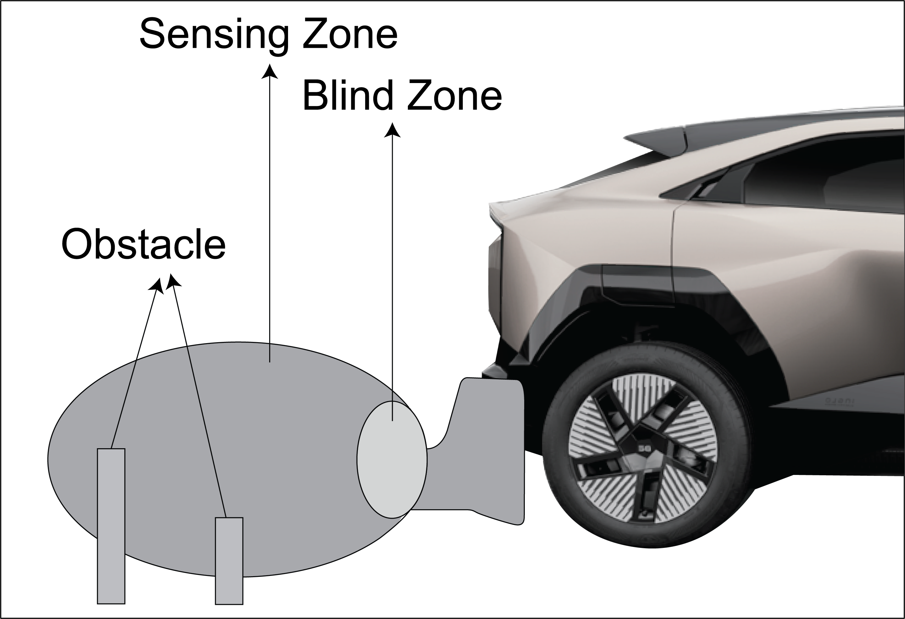
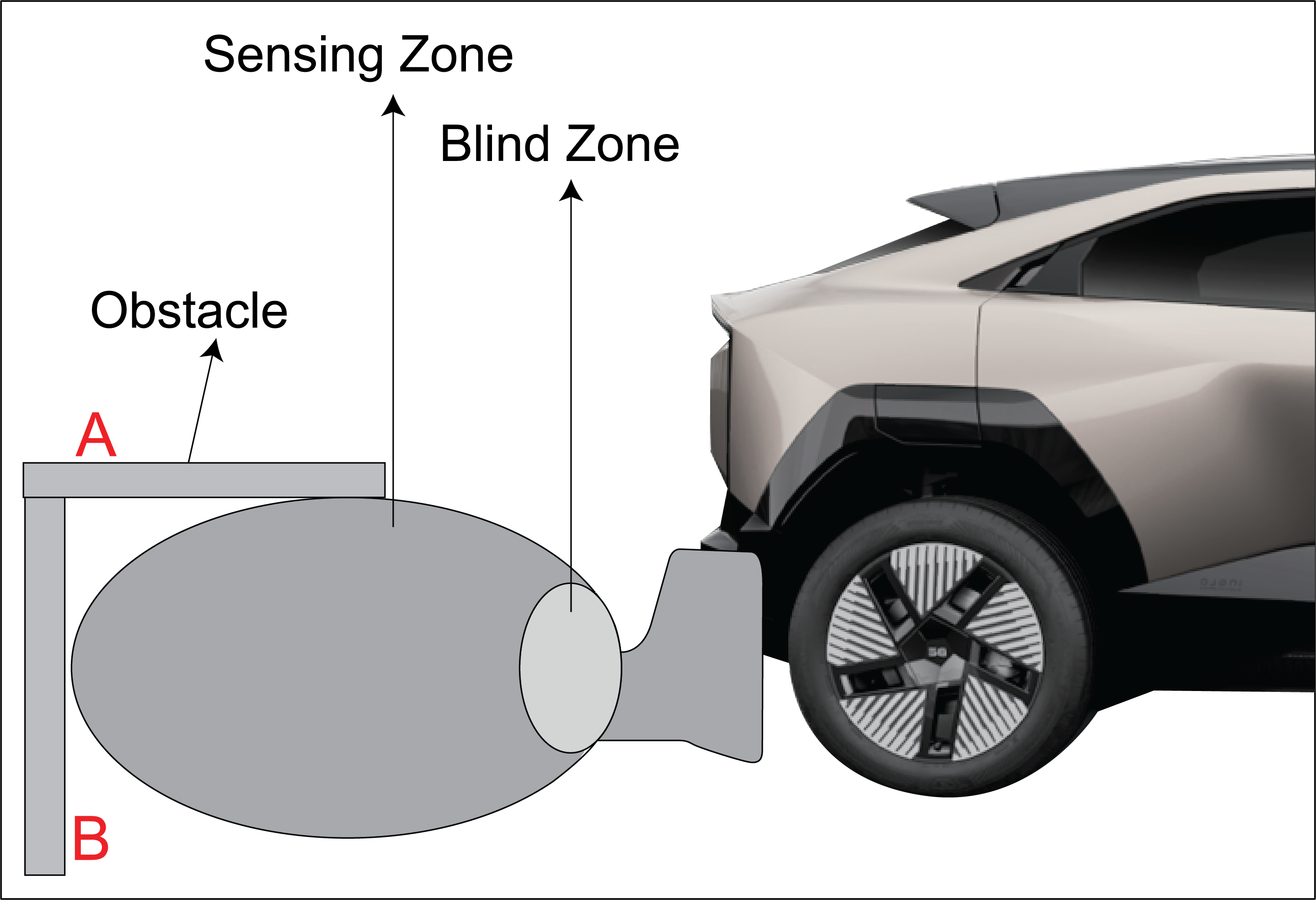
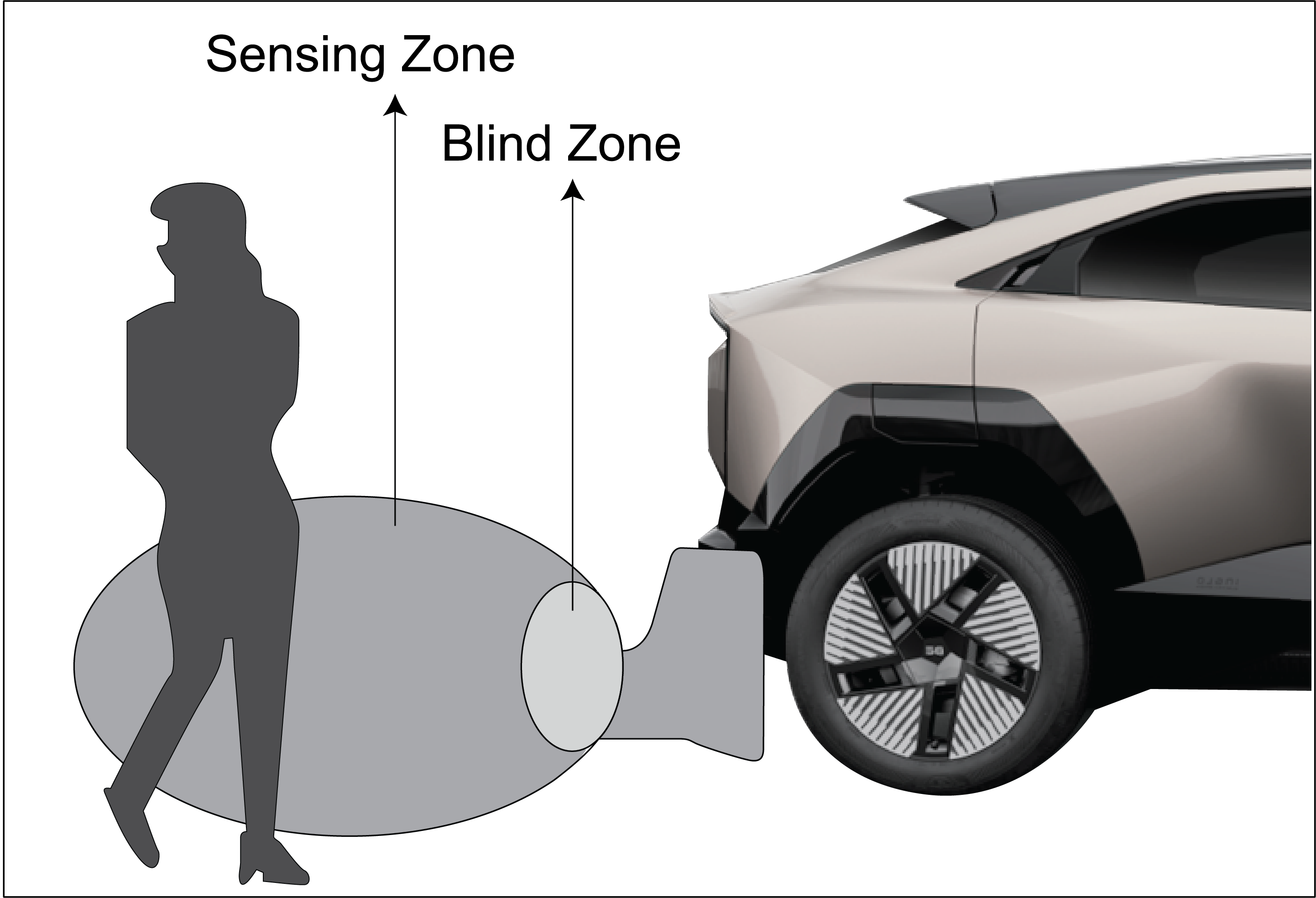
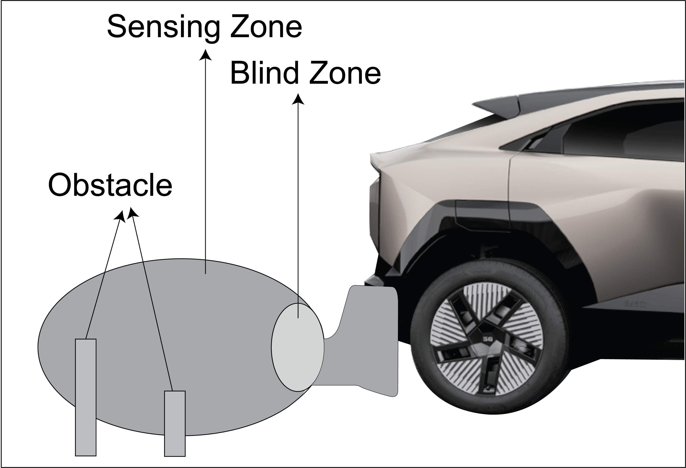
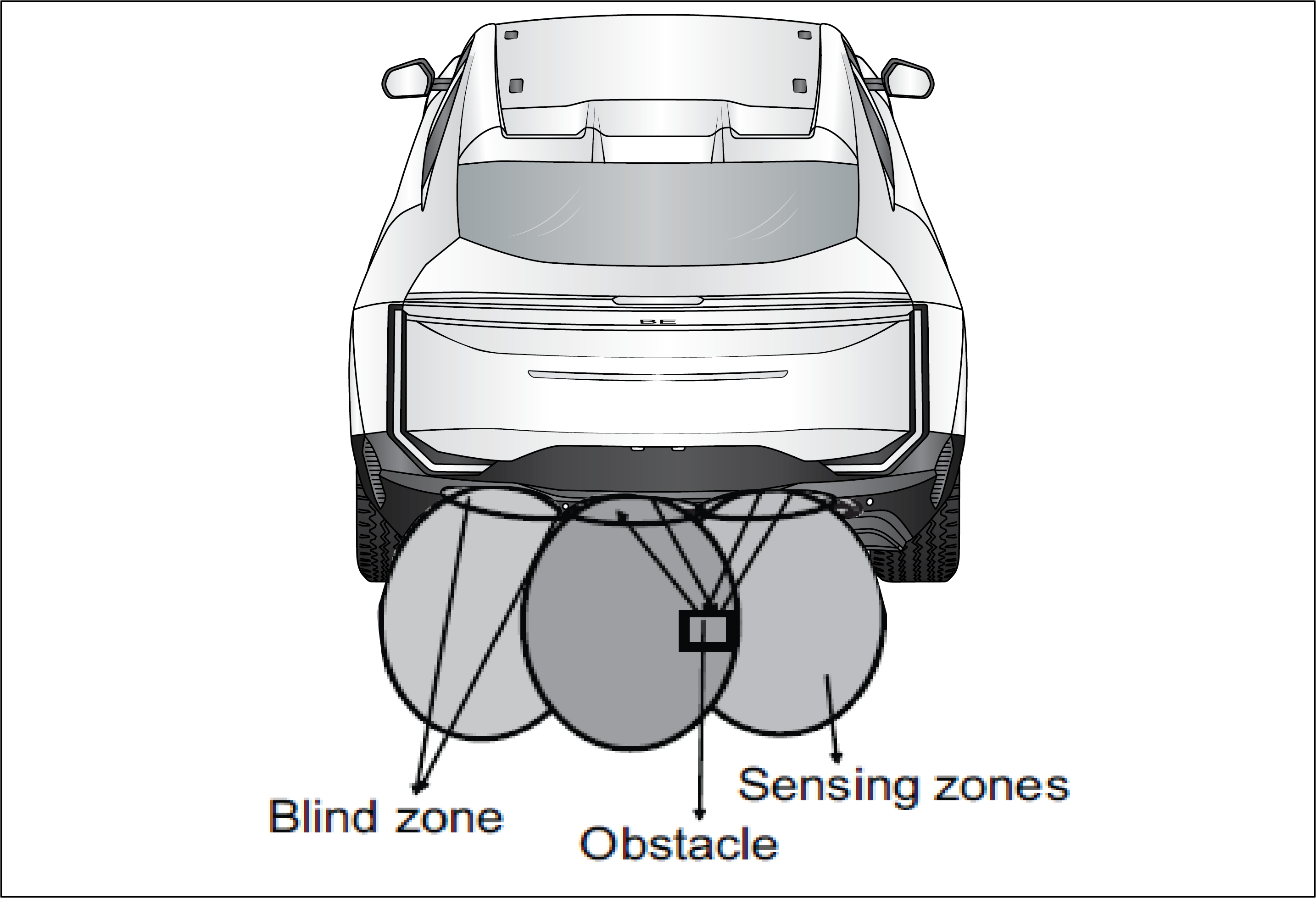
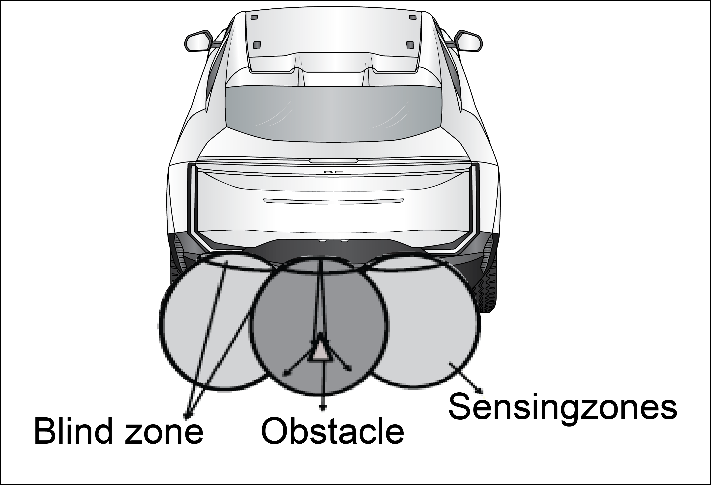
Blind spot detection Telltale |
It indicates the Vehicle running in AEBS OFF (Autonomous Emergency Braking system) condition. Blind-spot monitoring uses sensors
on the outside of the car to keep an eye on your blind spot. If these sensors detect a car in your blind spot where it might
not be visible in your mirrors, a little light will turn on to let you know. The blind spot detection system reduces the risk
of accidents during lane changes by monitoring the dangerous blind spot area
Abnormal Operation:
If no vehicle passes and lamp is ON and ADAS System is not working
Actions recommended:
Contact Nearest Mahindra Authorised Service Centre.
|
• |
Driver initiated lane change White |
The Driver-Initiated Lane Change White Tell-Tale indicates that the system has detected the driver’s request to change lanes,
and it is preparing to assist or monitor the process. This light is typically illuminated when the lane change assist system
is active but not yet fully engaged.
Actions recommended:
Use the turn signal to confirm your intention to change lanes. The system will respond accordingly if it detects a clear path.
|
• |
Driver initiated lane change Green |
The Driver-Initiated Lane Change Green Tell-Tale indicates that the lane change assist system has detected safe conditions
and is actively assisting or monitoring the execution of the lane change. This light confirms that the system is engaged and
the lane change is in progress.
Actions recommended:
Be ready to manually adjust or abort the lane change if the system fails to execute the maneuver correctly. If the tell-tale
switches back to white or another color (e.g., yellow), reassess traffic conditions and proceed with manual intervention if
required.
|
• |
Driver initiated lane change Yellow |
The Driver-Initiated Lane Change Yellow Tell-Tale indicates that the lane change assist system has encountered an issue or
cannot proceed safely with the lane change. This warning signals that the system requires driver intervention to complete
or abort the maneuver.
Actions recommended:
Abort or manually complete the lane change as required.
|
• |
Control Cruise Nav White |
The Control Cruise Navigation White Tell-Tale indicates that the cruise control system is powered on and in standby mode,
ready to be activated. This tell-tale confirms that the system is operational but not actively controlling the vehicle's speed.
Actions recommended:
Turn off cruise control when navigating through heavy traffic, adverse weather, or on curvy or hilly roads.
|
• |
Control Cruise Nav Green |
The Control Cruise Navigation Green Tell-Tale indicates that the cruise control system is actively engaged and is controlling
the vehicle's speed. This tell-tale signifies that the vehicle is currently operating in cruise control mode, allowing the
driver to maintain a constant speed without needing to press the accelerator pedal.
Actions recommended:
Turn off cruise control if road conditions become unsafe or if you need to make frequent speed adjustments. Keep your hands
on the steering wheel and be ready to intervene if road conditions change.
|
• |
Control Cruise Nav Yellow |
The Control Cruise Navigation Yellow Tell-Tale serves as a warning that the cruise control system is experiencing an issue
or is not functioning as intended. This tell-tale may indicate that while the system is engaged, there are conditions that
require the driver’s attention or intervention.
Actions recommended:
If the yellow tell-tale remains illuminated or if you experience difficulties with the cruise control system, contact a qualified
technician for diagnosis and repair
|
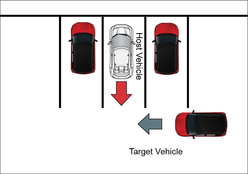
• |
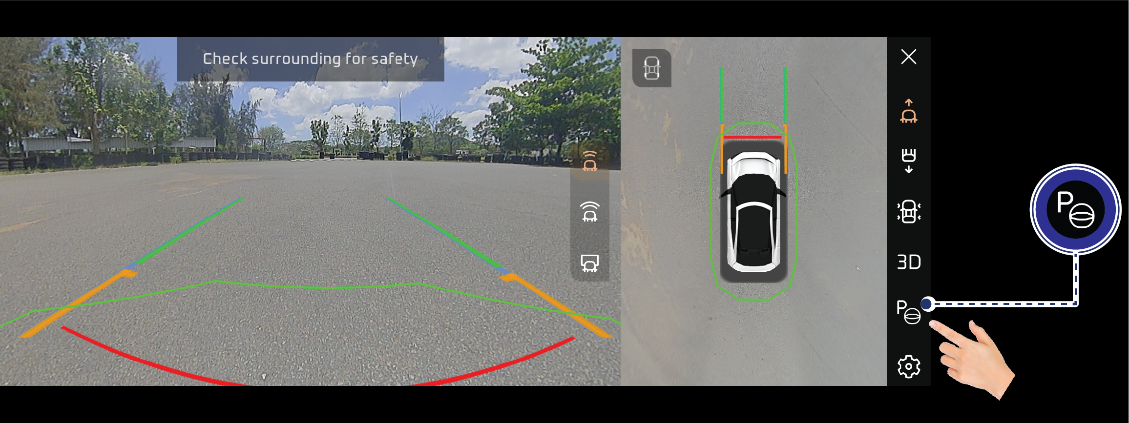
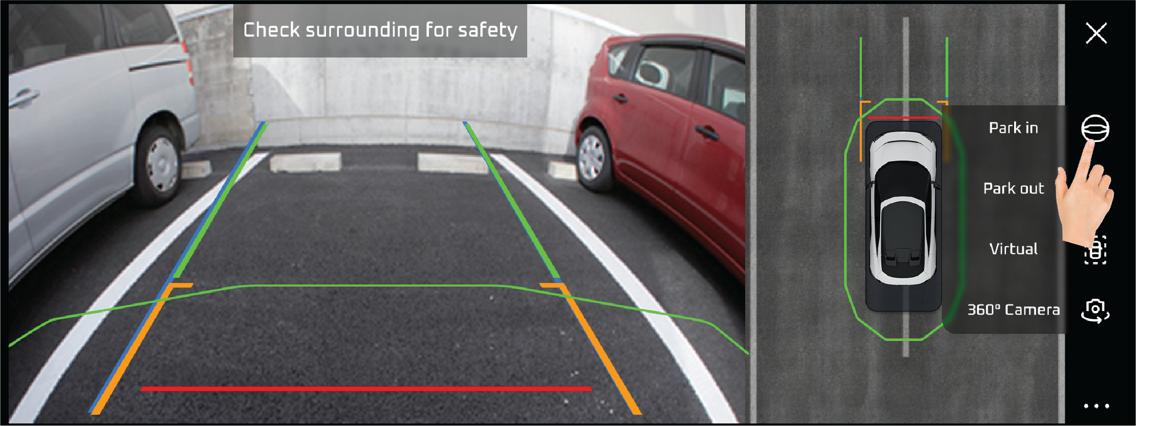
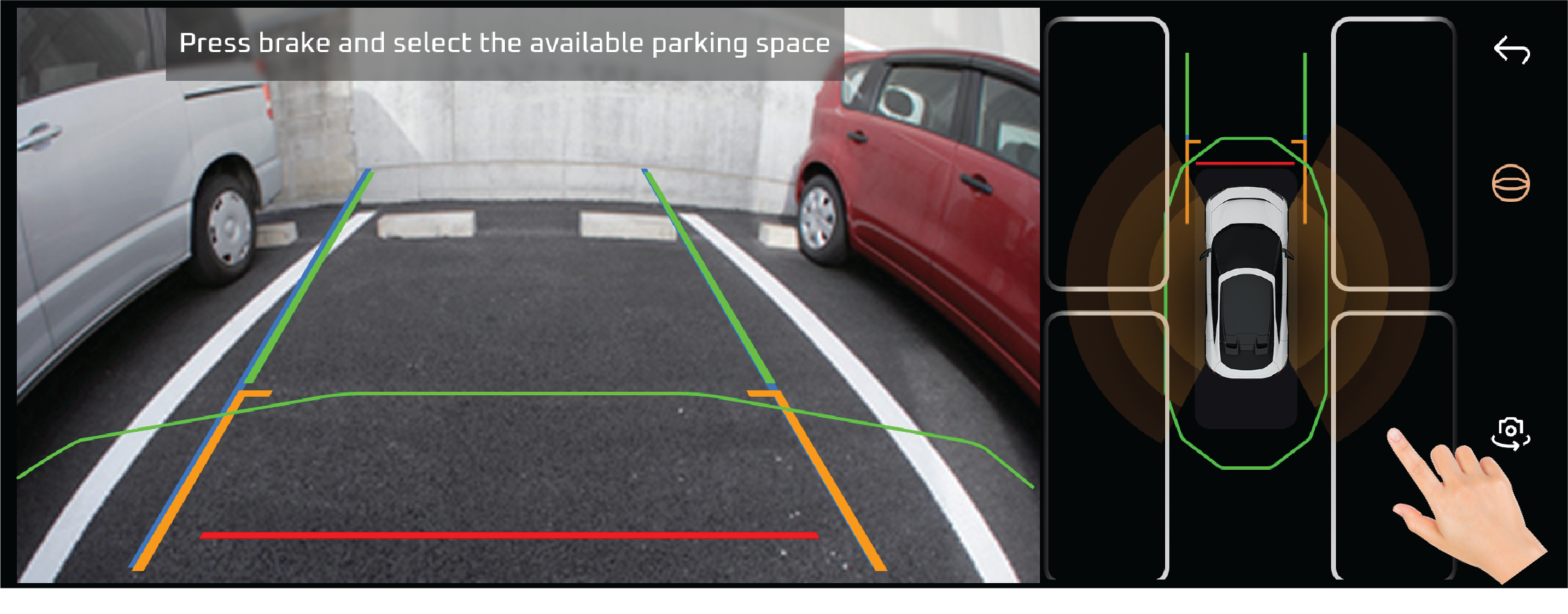
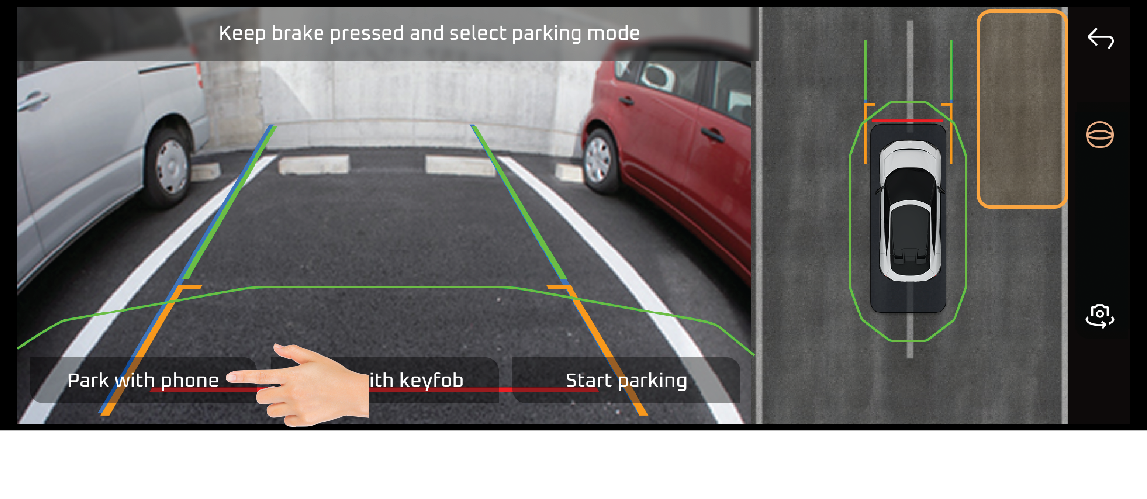
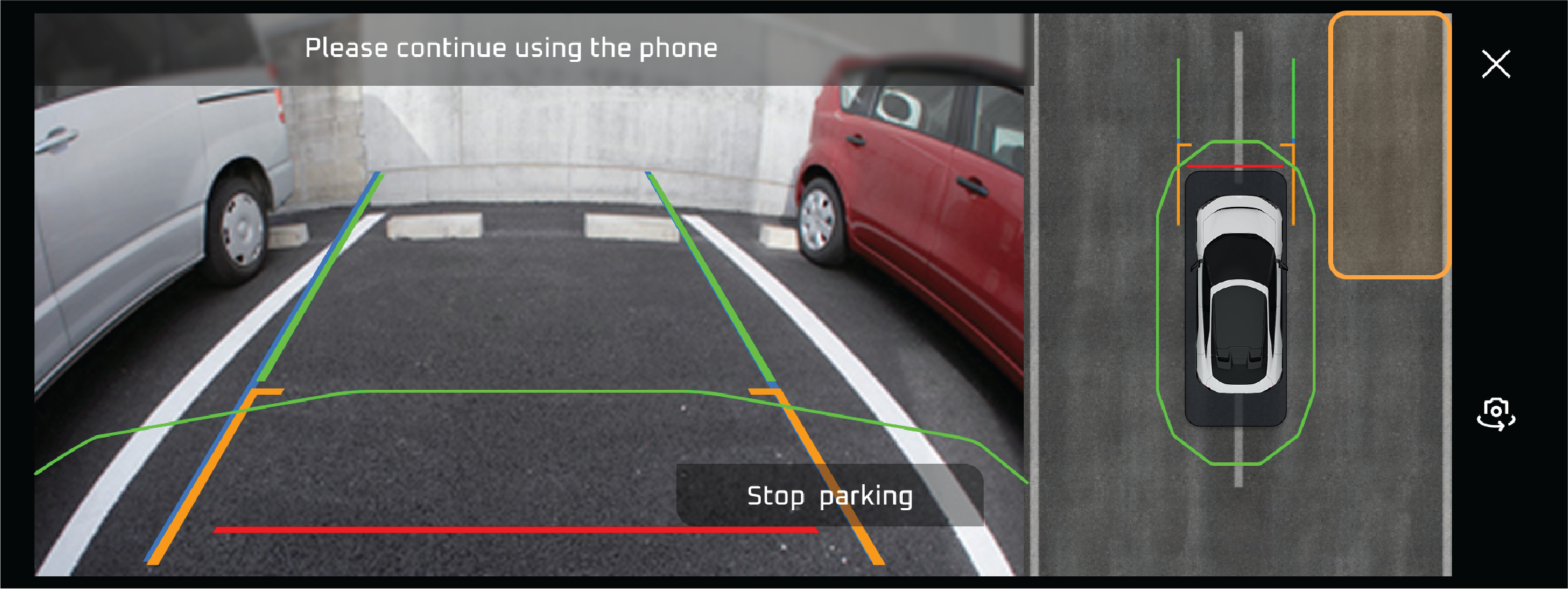
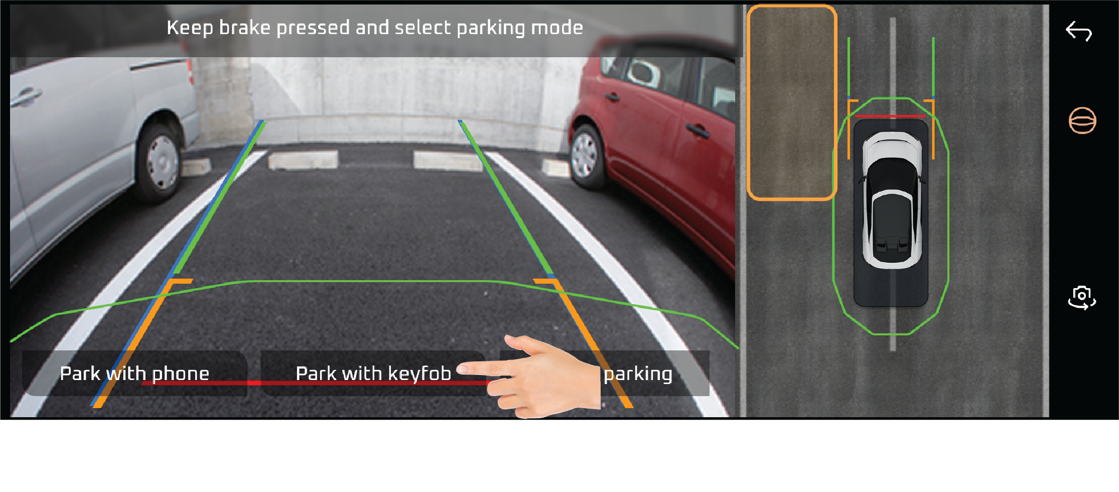
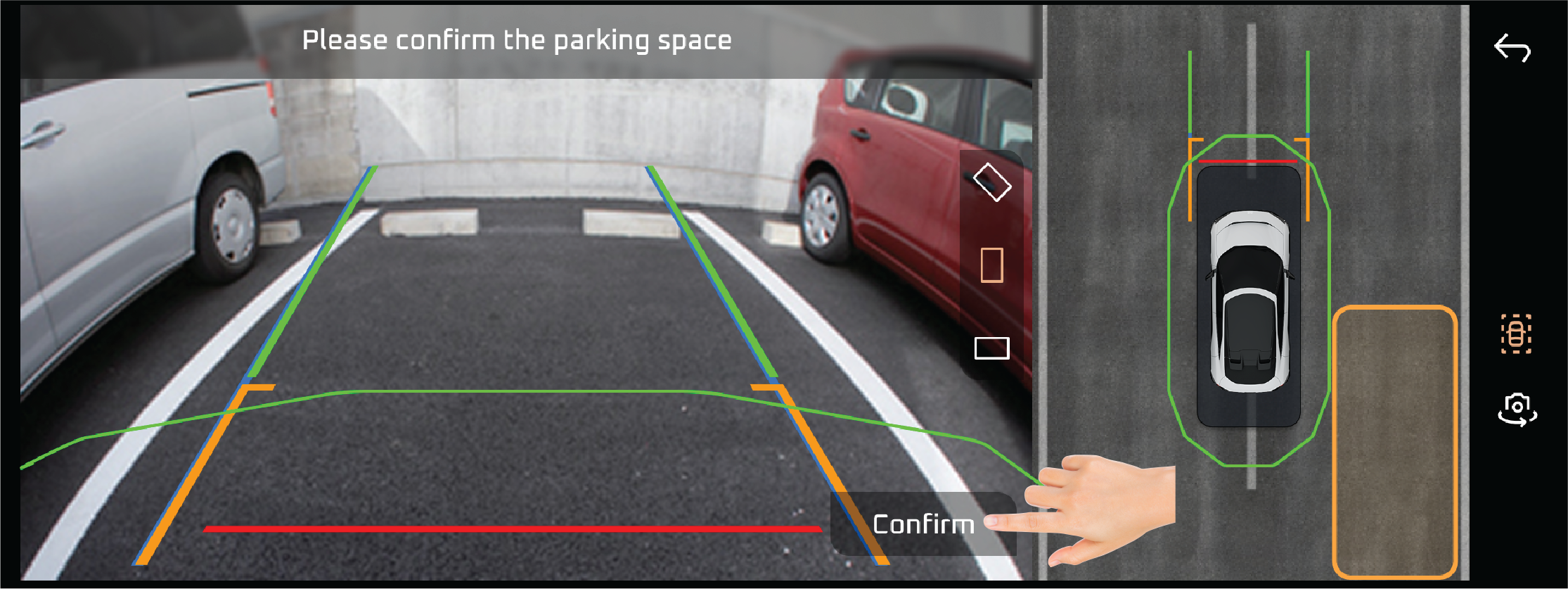
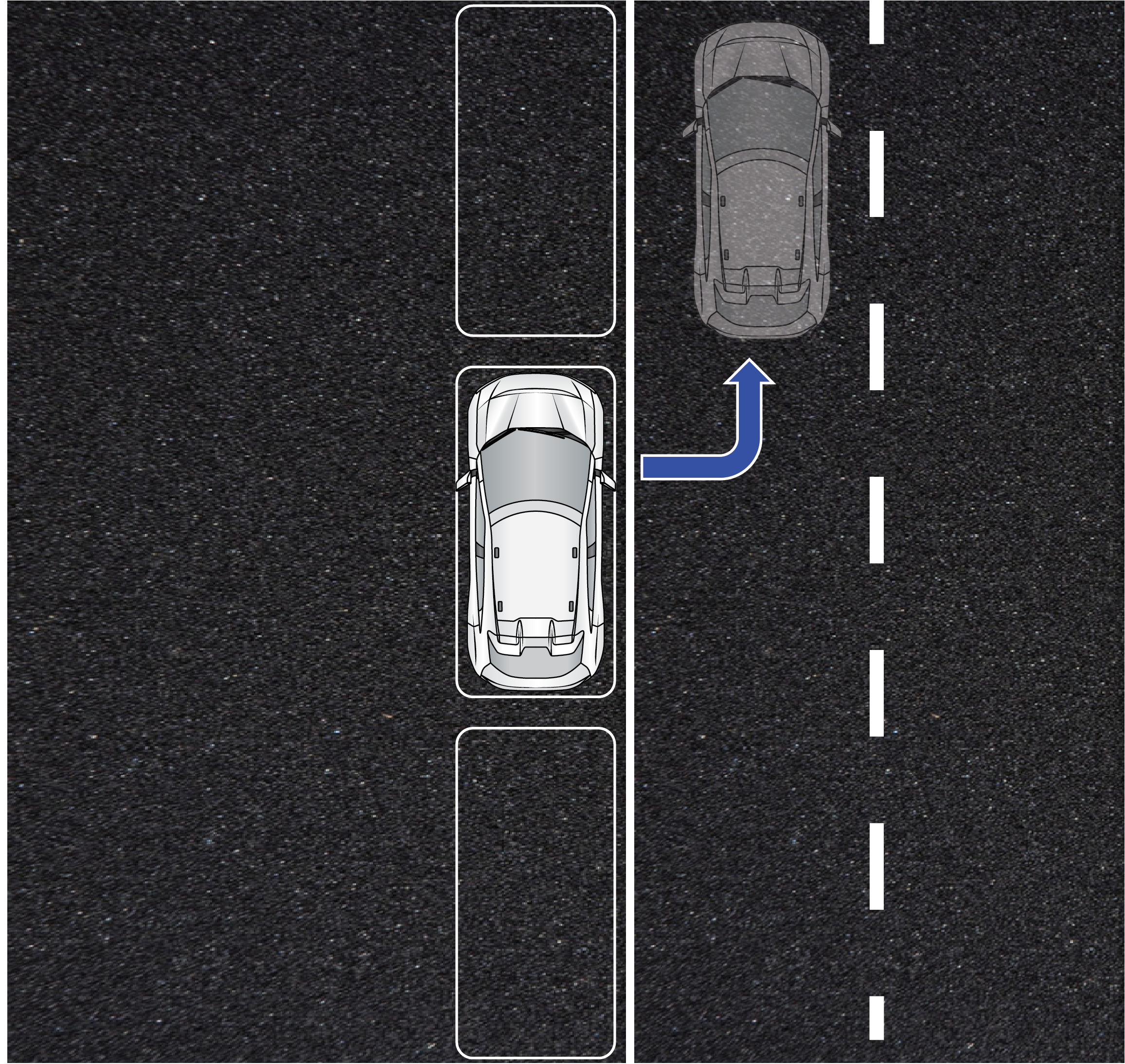
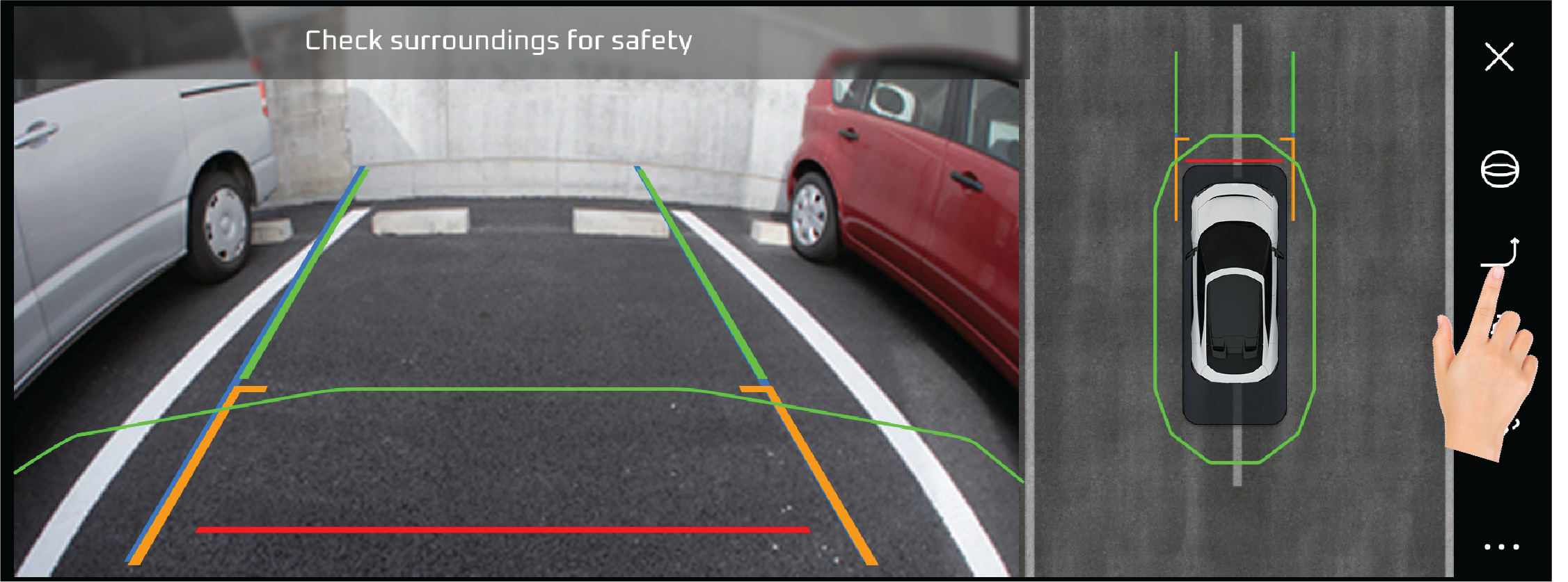
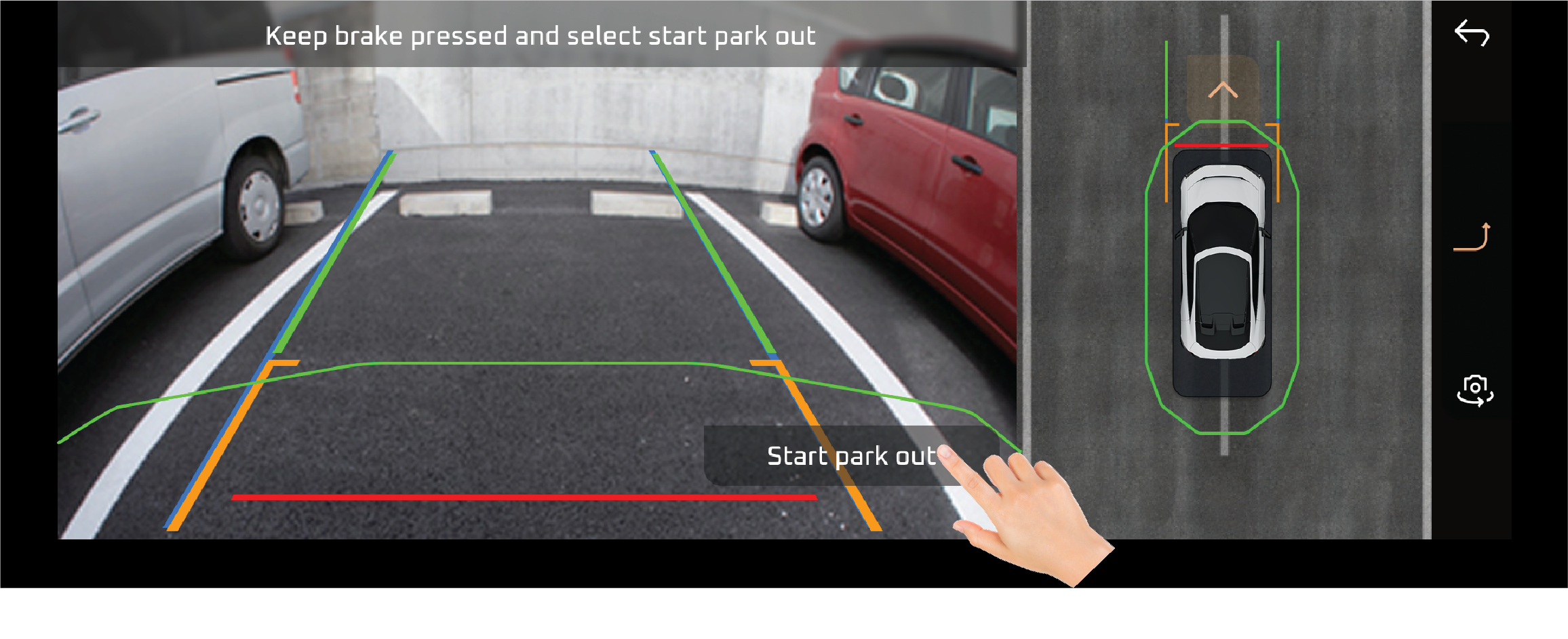
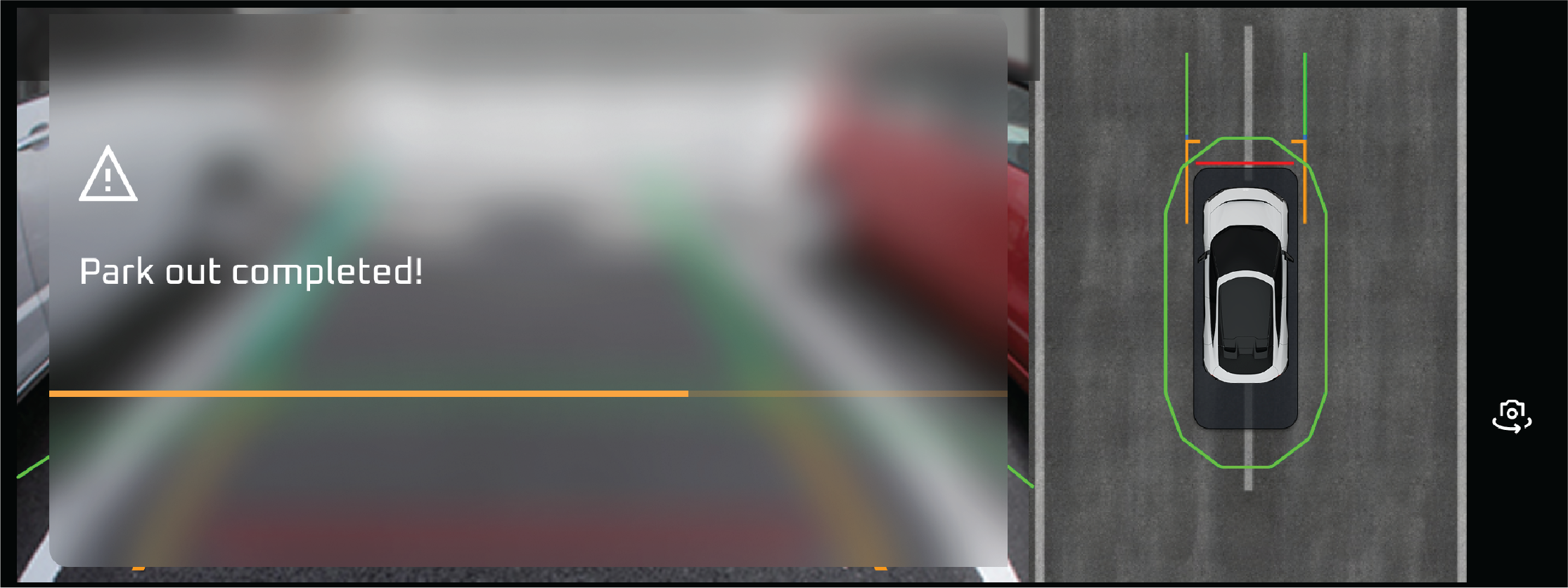
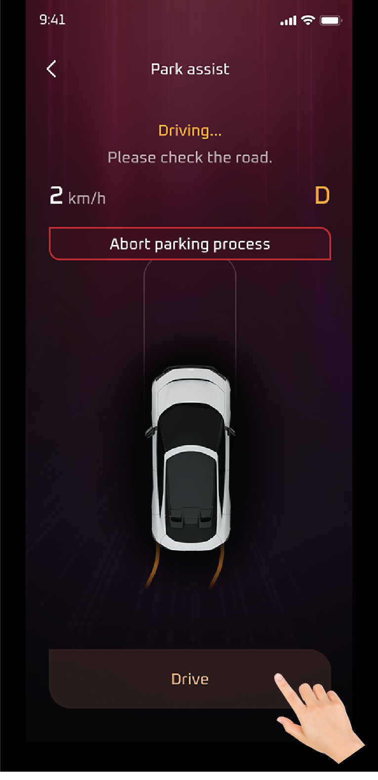
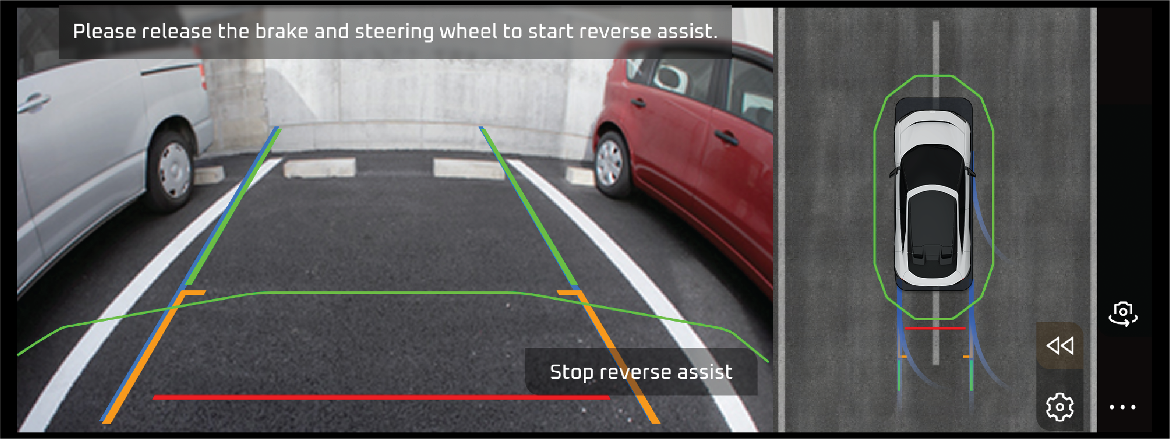
Smart Parking Assist White |
The Smart Parking Assist White Tell-Tale indicates that the Smart Parking Assist system is active and ready for operation.
This feature assists the driver with parking maneuvers by using sensors and automated steering controls to guide the vehicle
into a parking space.
Actions recommended:
Continuously check mirrors and surroundings for unexpected obstacles or hazards that the system might not detect.
|
• |
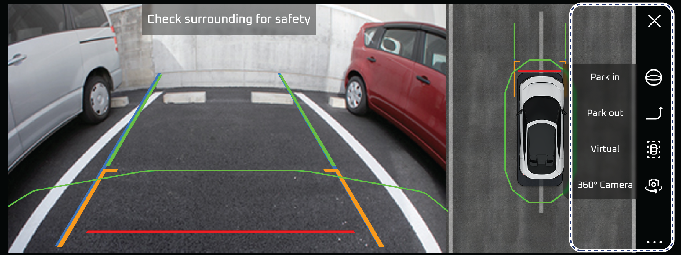
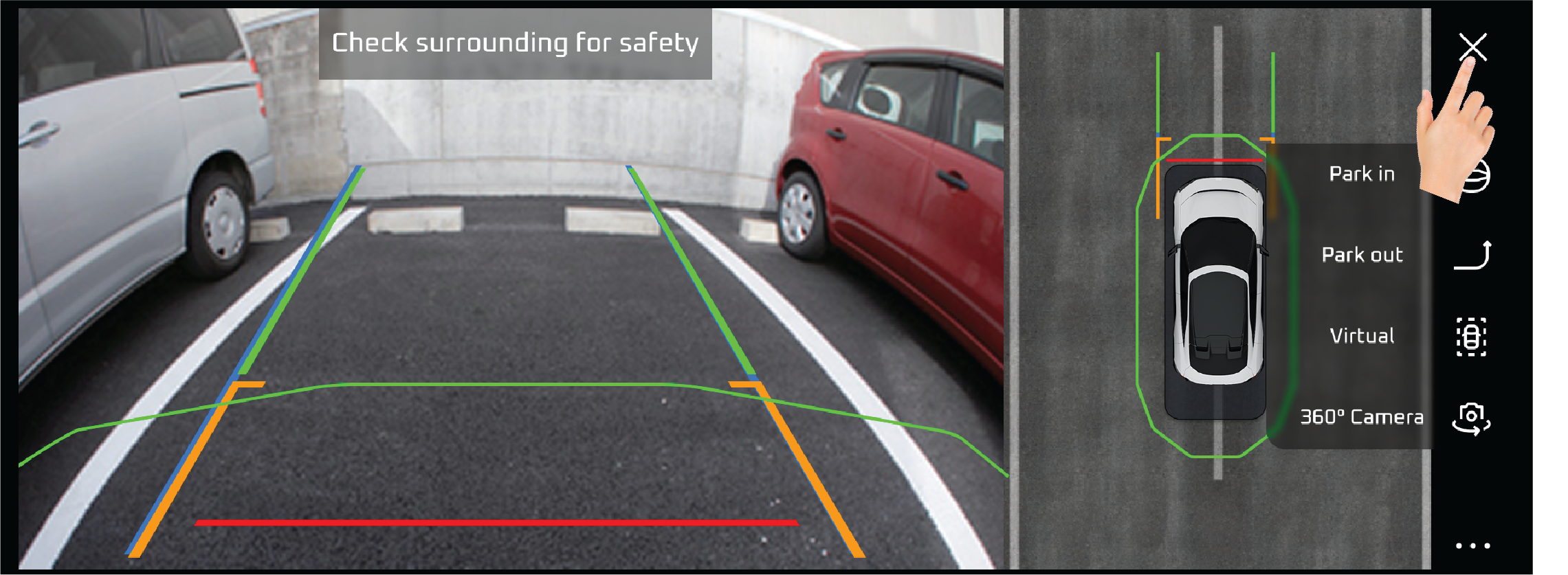
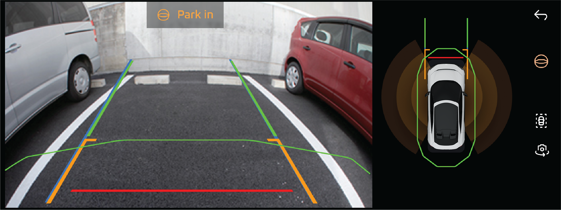
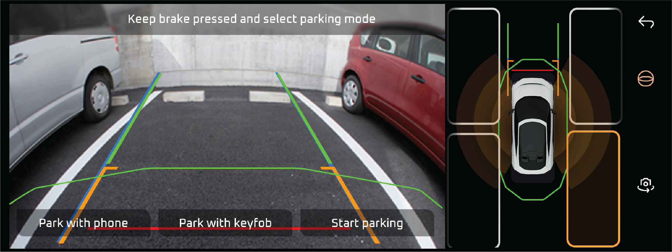
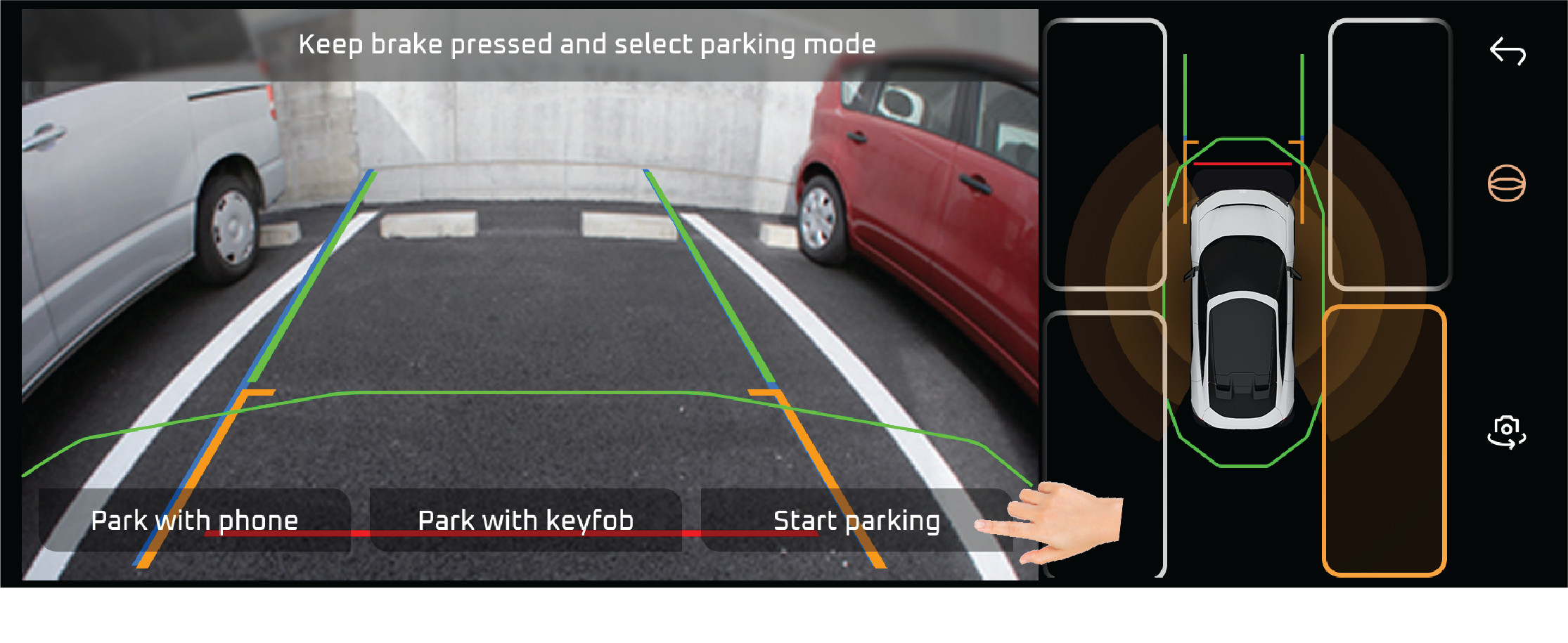
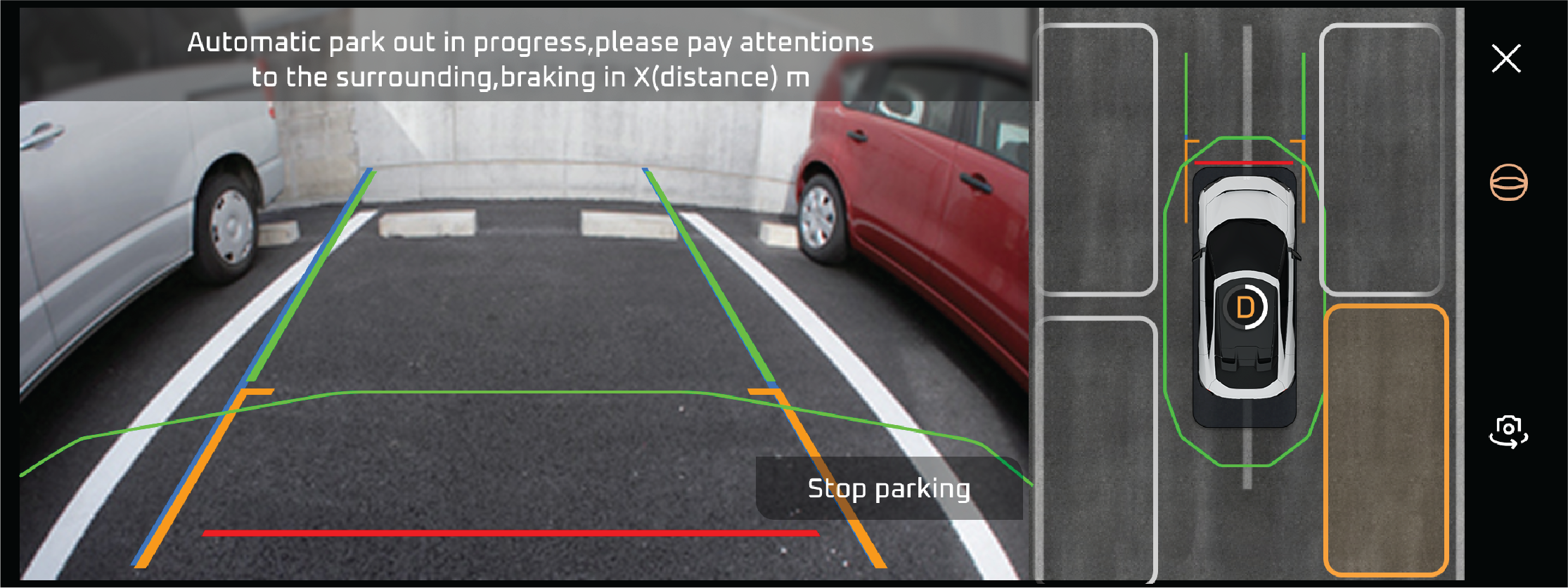
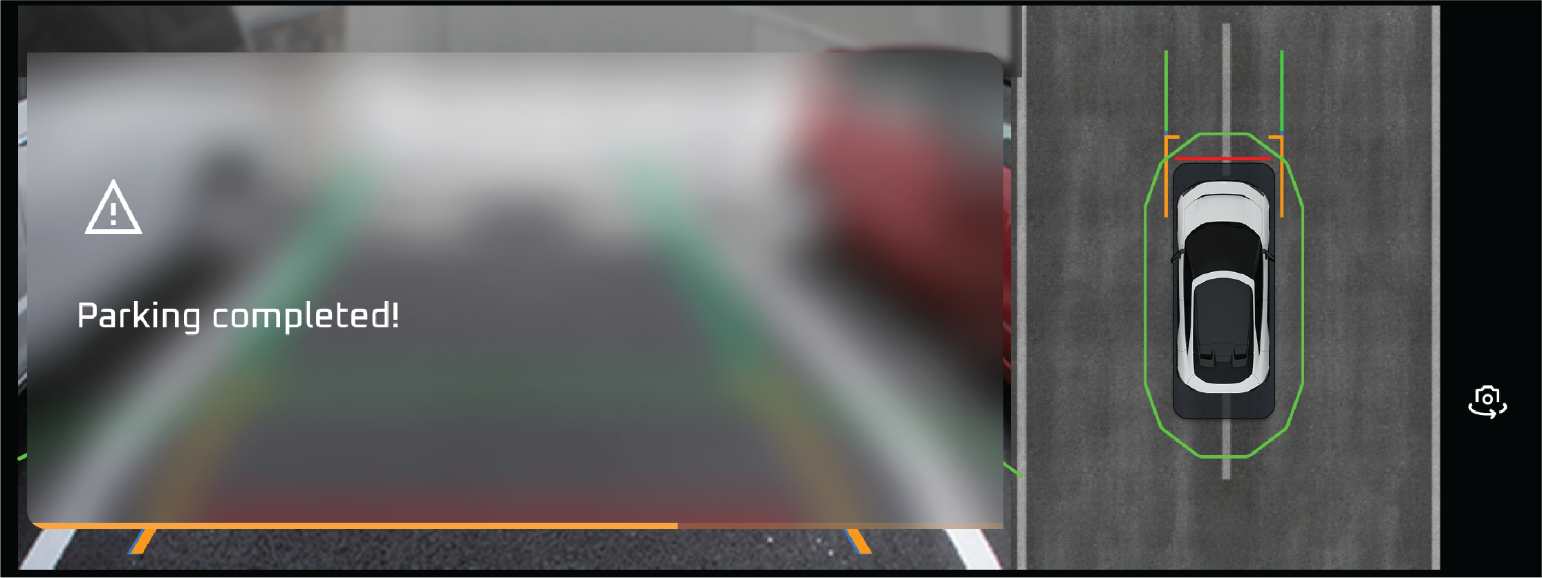
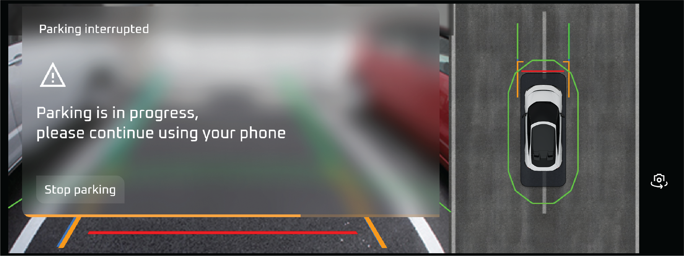
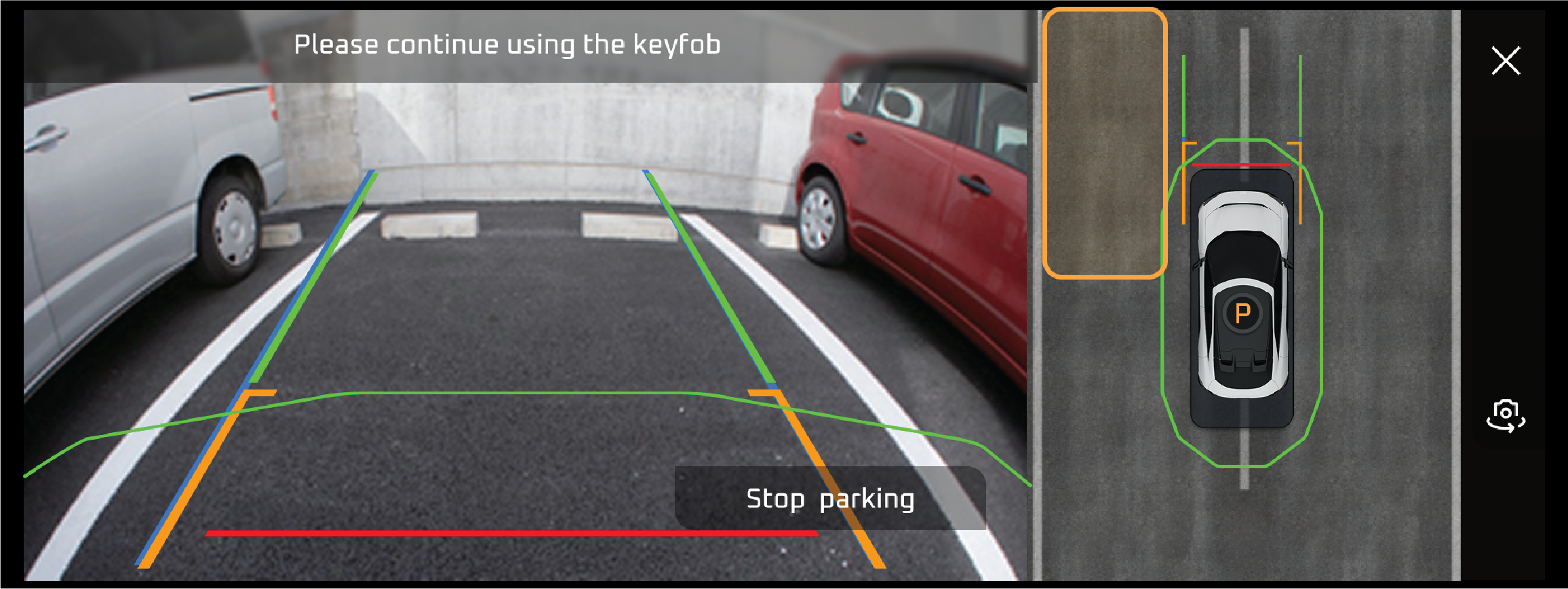
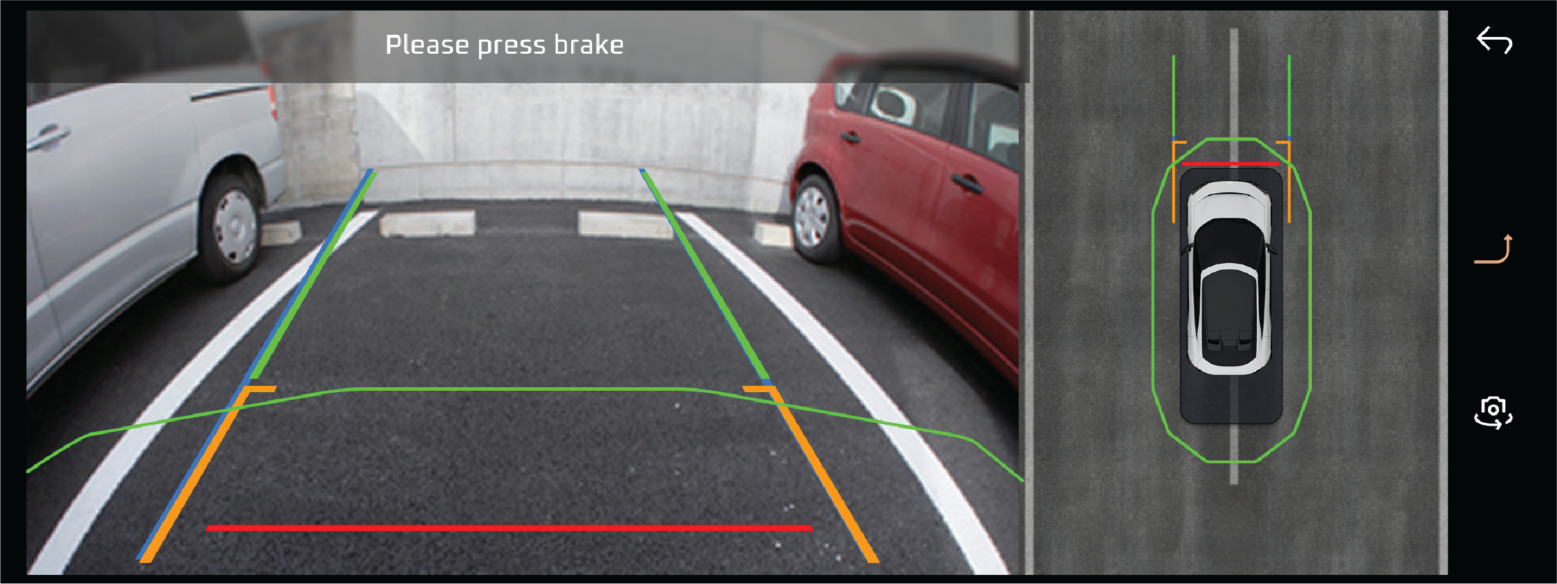
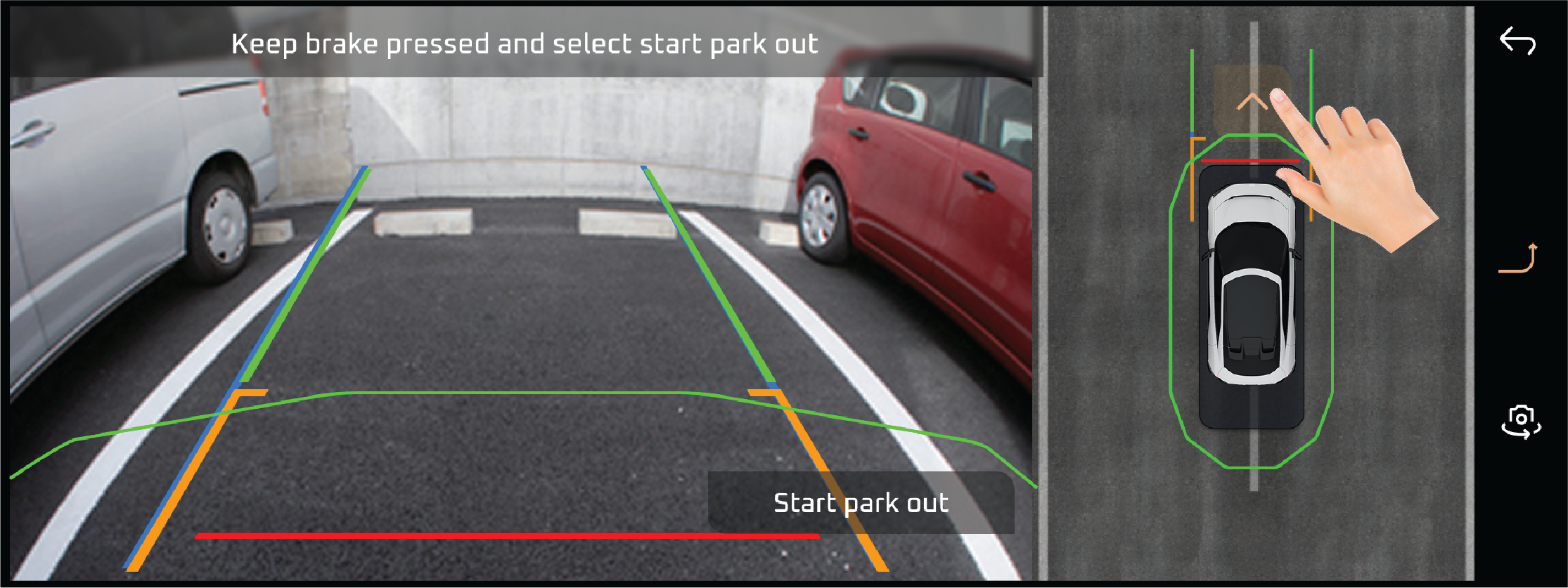
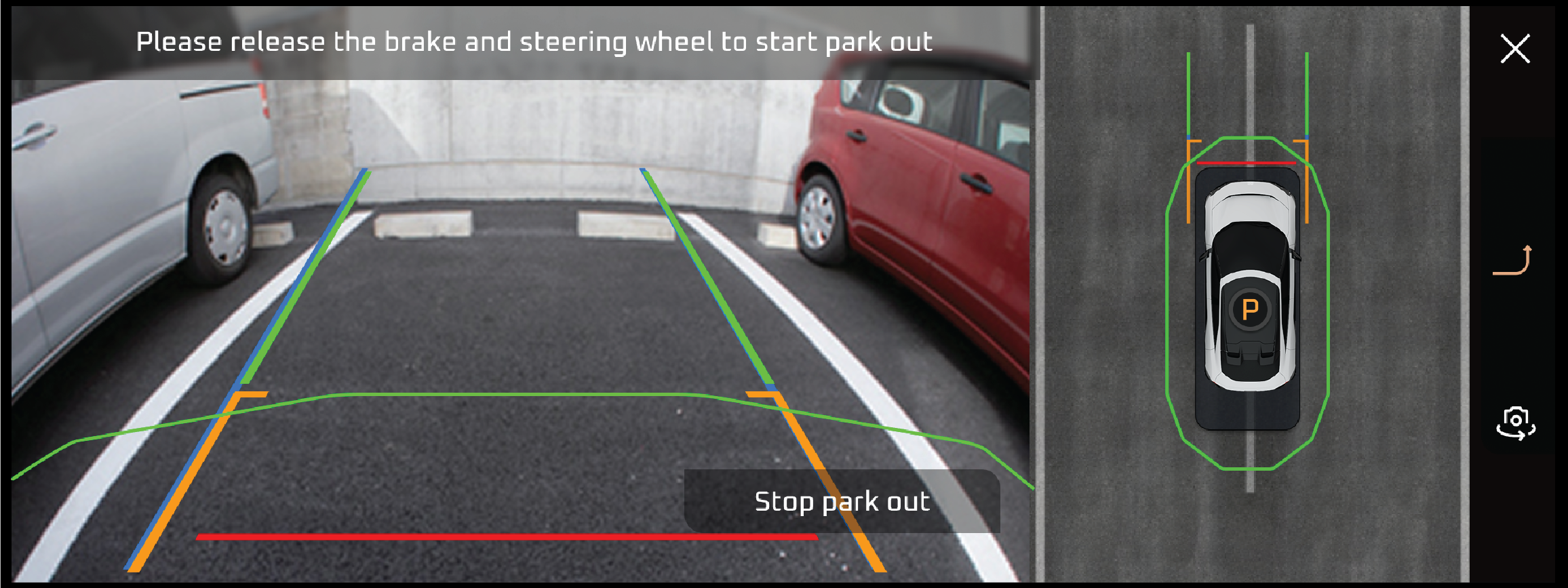
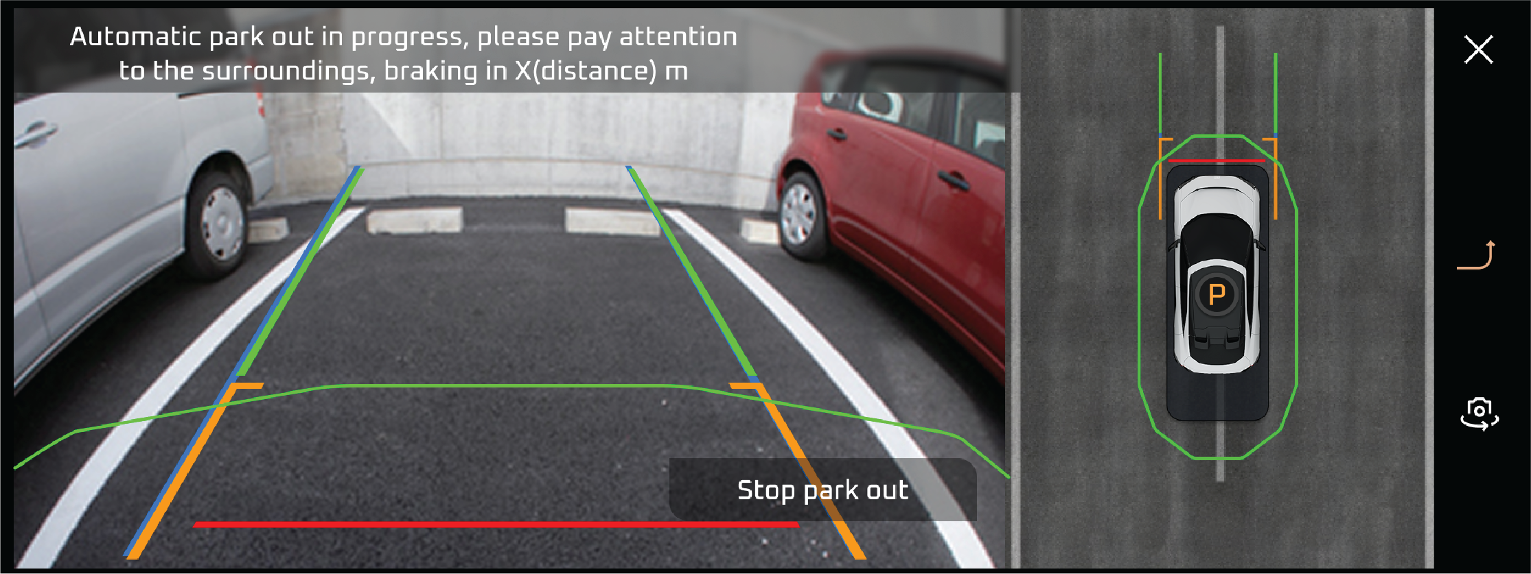
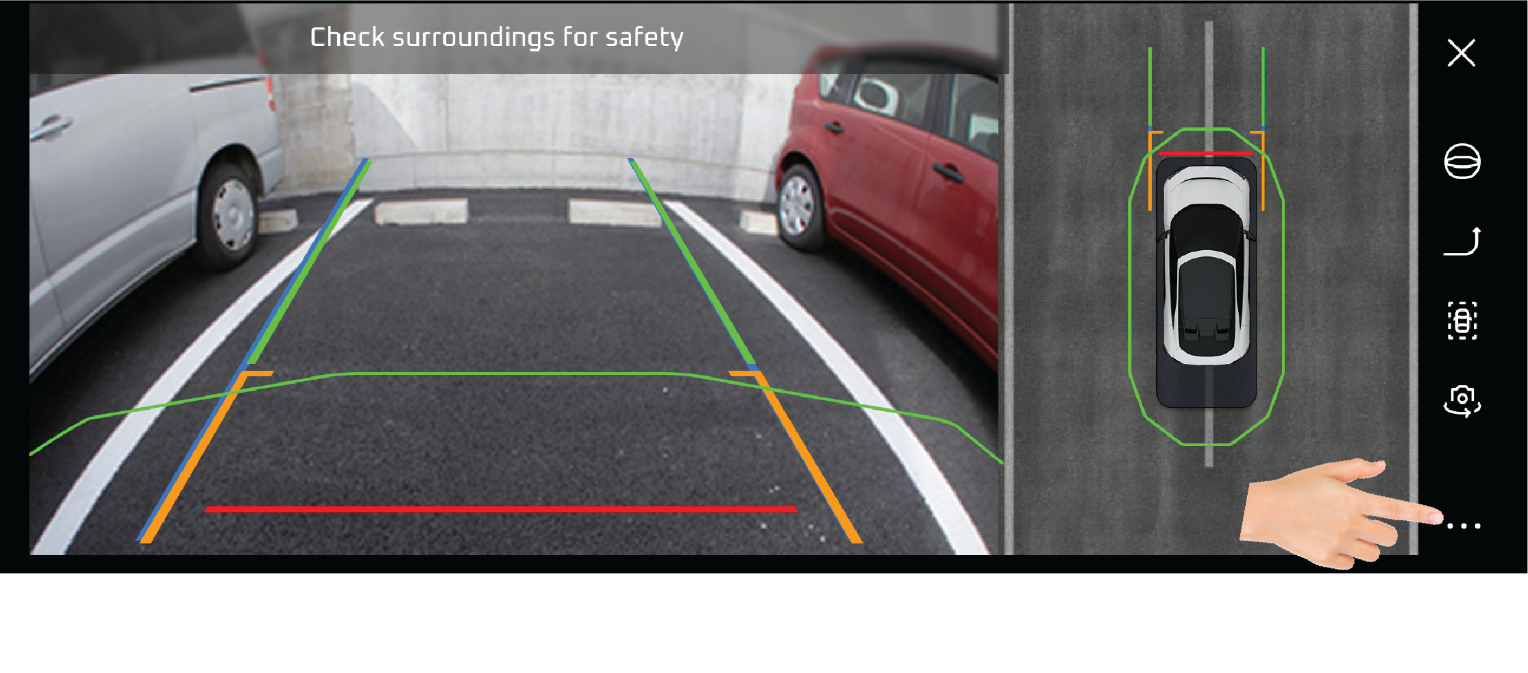
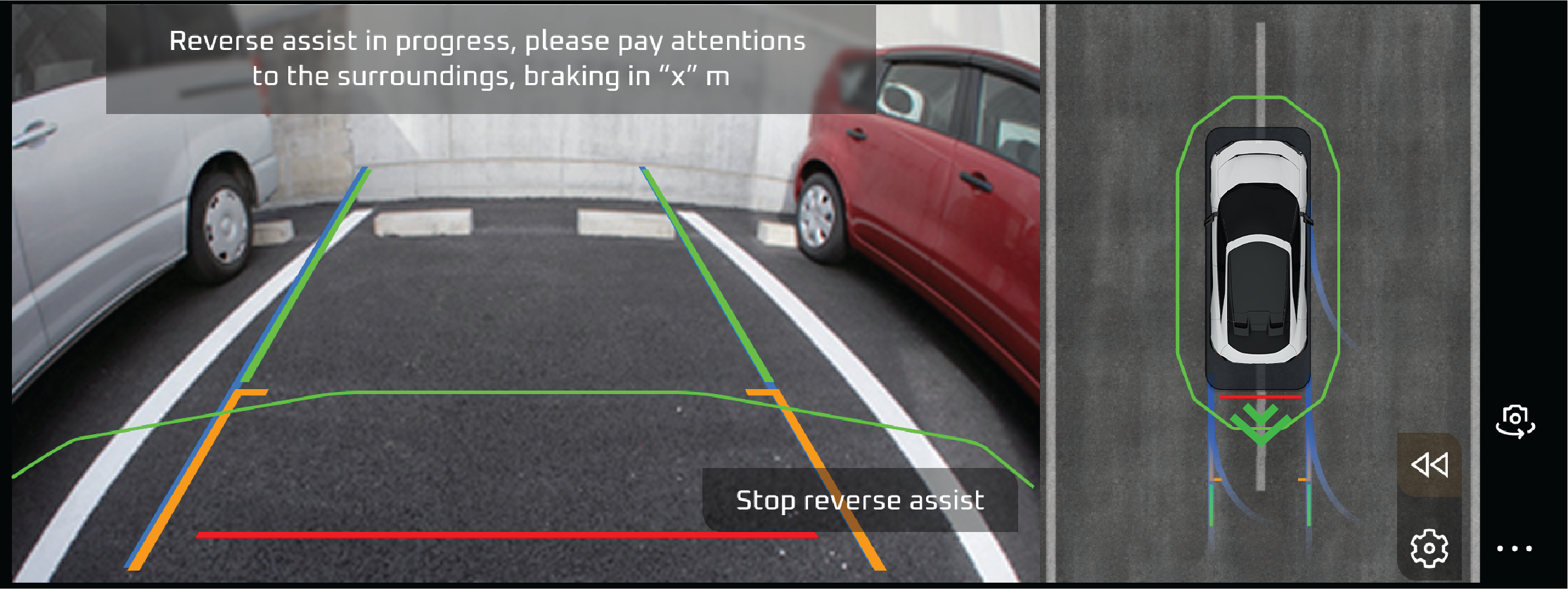
Smart Parking Assist Green |
The Smart Parking Assist Green Tell-Tale indicates that the Smart Parking Assist system is actively engaged and currently
maneuvering the vehicle into a parking spot. This means the system is in control of steering, and in some cases, throttle
and braking, depending on the vehicle's features.
Actions recommended:
Even though the system is engaged, remain attentive and monitor the surroundings to ensure safety
|
• |
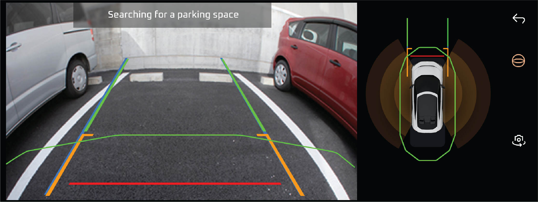
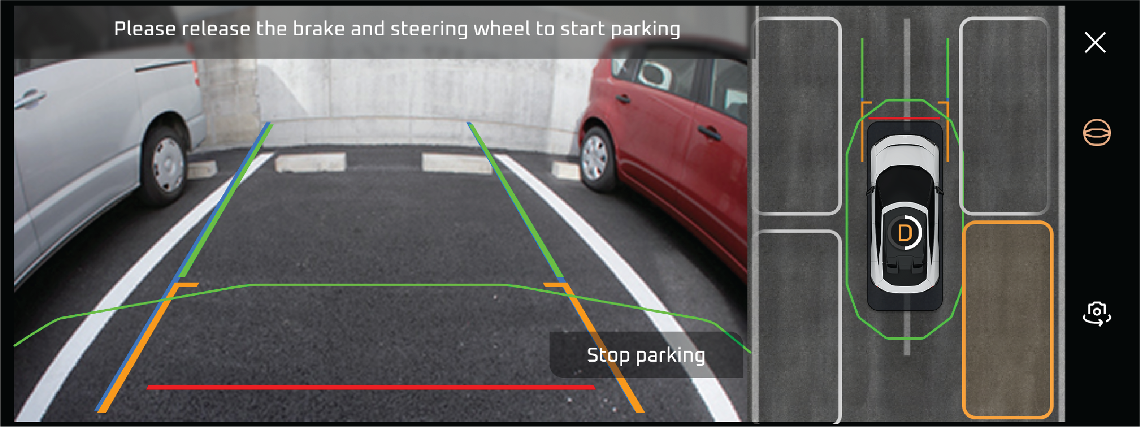
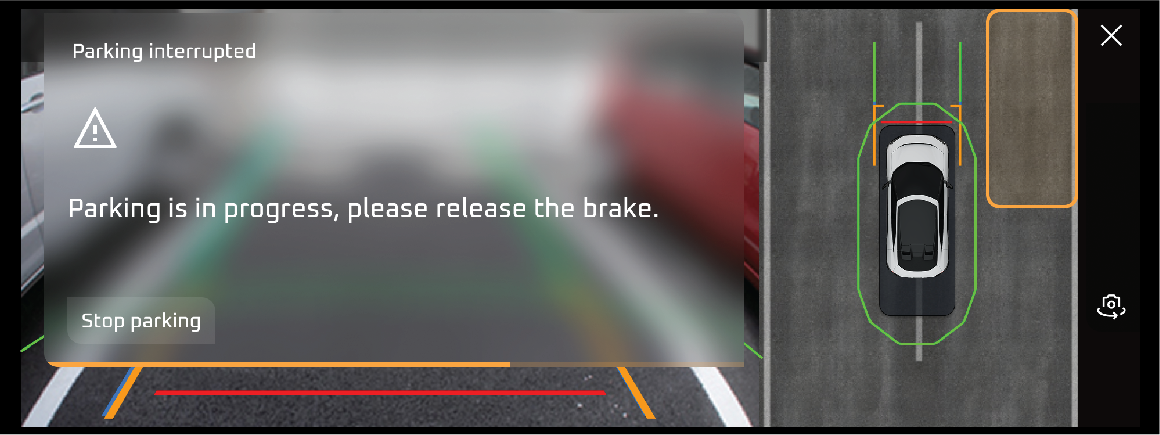
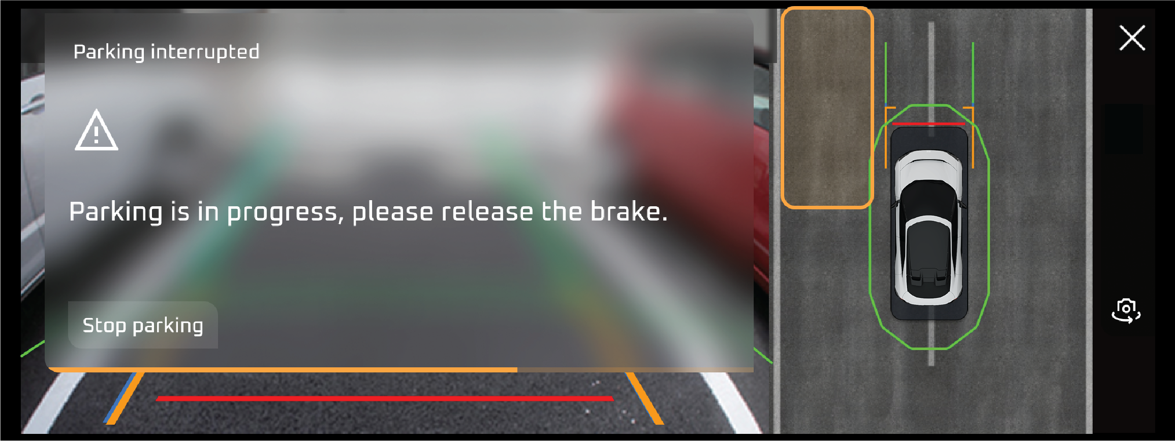
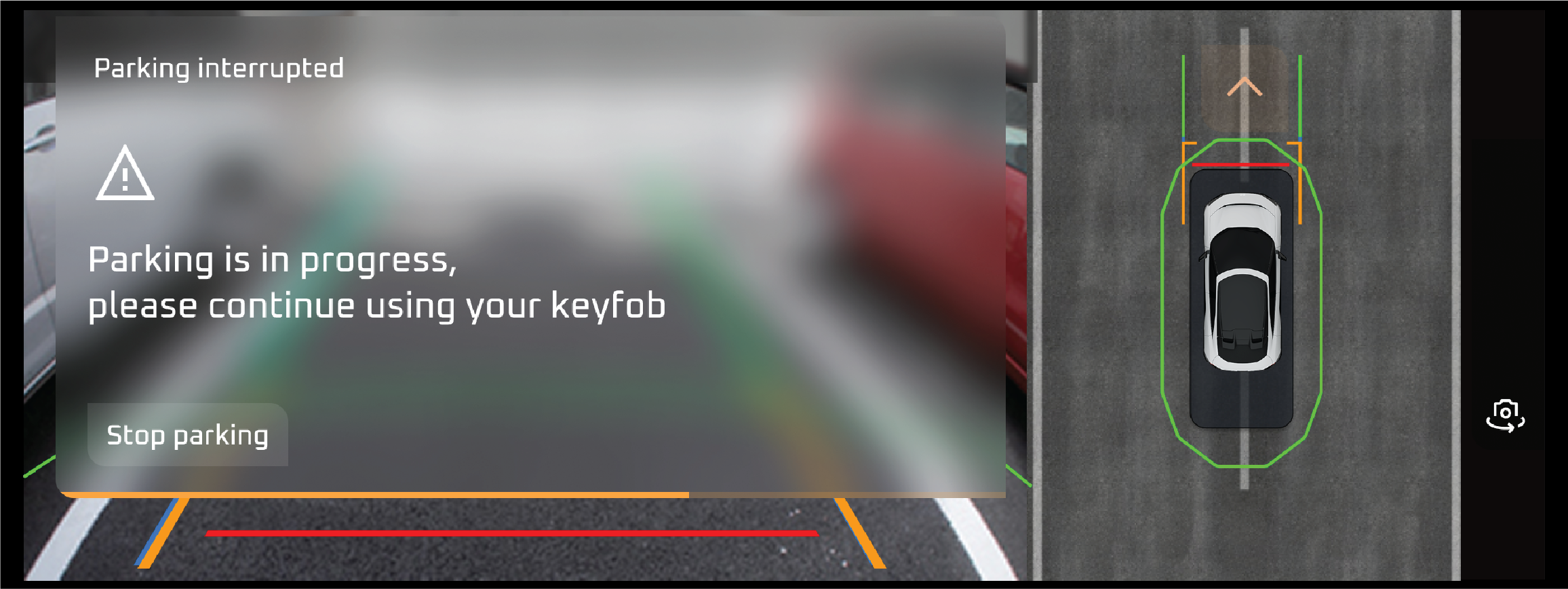
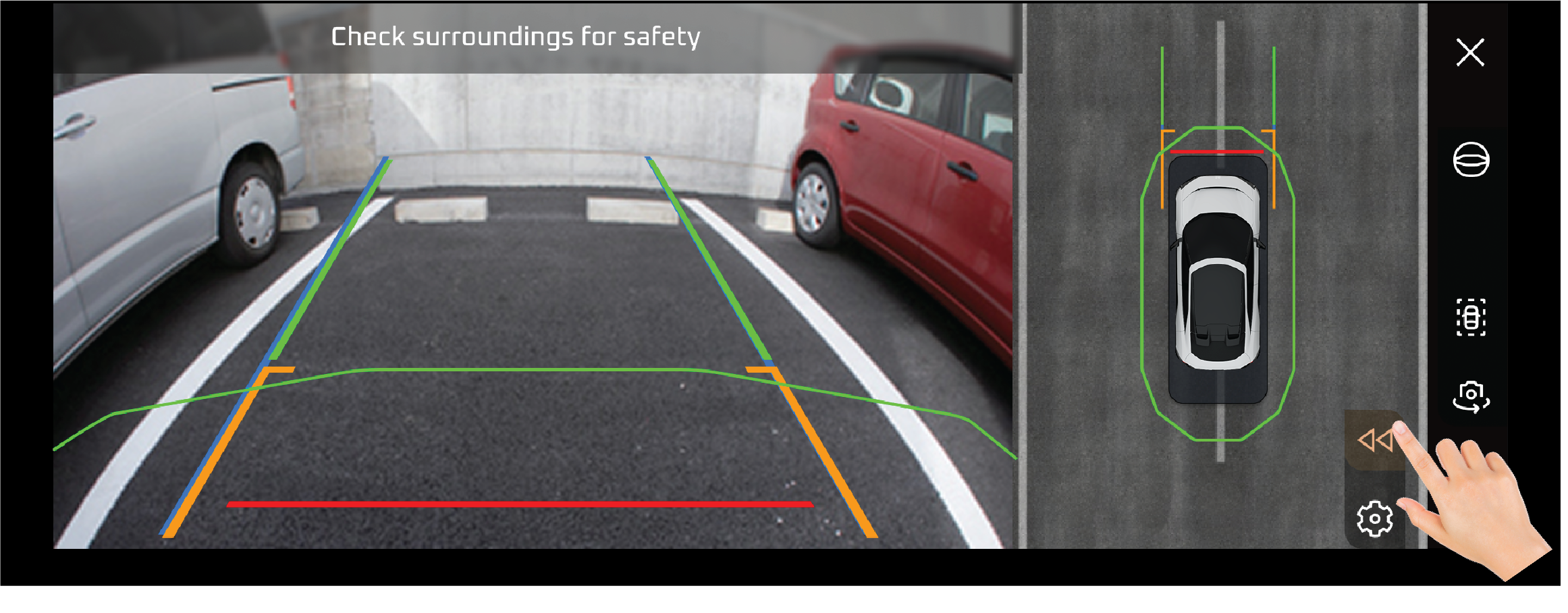
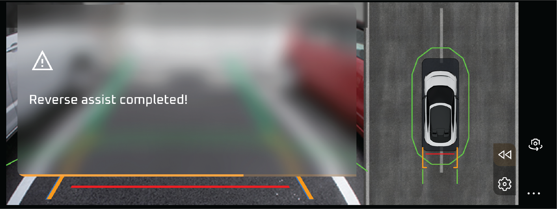
Smart Parking Assist Yellow |
The Smart Parking Assist Yellow Tell-Tale indicates that the Smart Parking Assist system has encountered an issue or is temporarily
unavailable due to specific conditions. This warning suggests the system may not function as expected.
Actions recommended:
Inspect the surroundings of the vehicle to ensure no debris or obstacles are blocking the sensors or cameras.
The Suspension System Tell-Tale illuminates when there is an issue with the vehicle's suspension system, such as a malfunction
in the adaptive suspension, air suspension, or shock absorbers. It may appear as a yellow or red warning light, depending
on the severity of the issue.
Actions recommended:
Drive slowly and carefully to prevent further damage to the suspension system Check for any obvious signs of damage, such
as a low ride height or uneven suspension and Contact Mahindra Authorised Service Center for assistance.
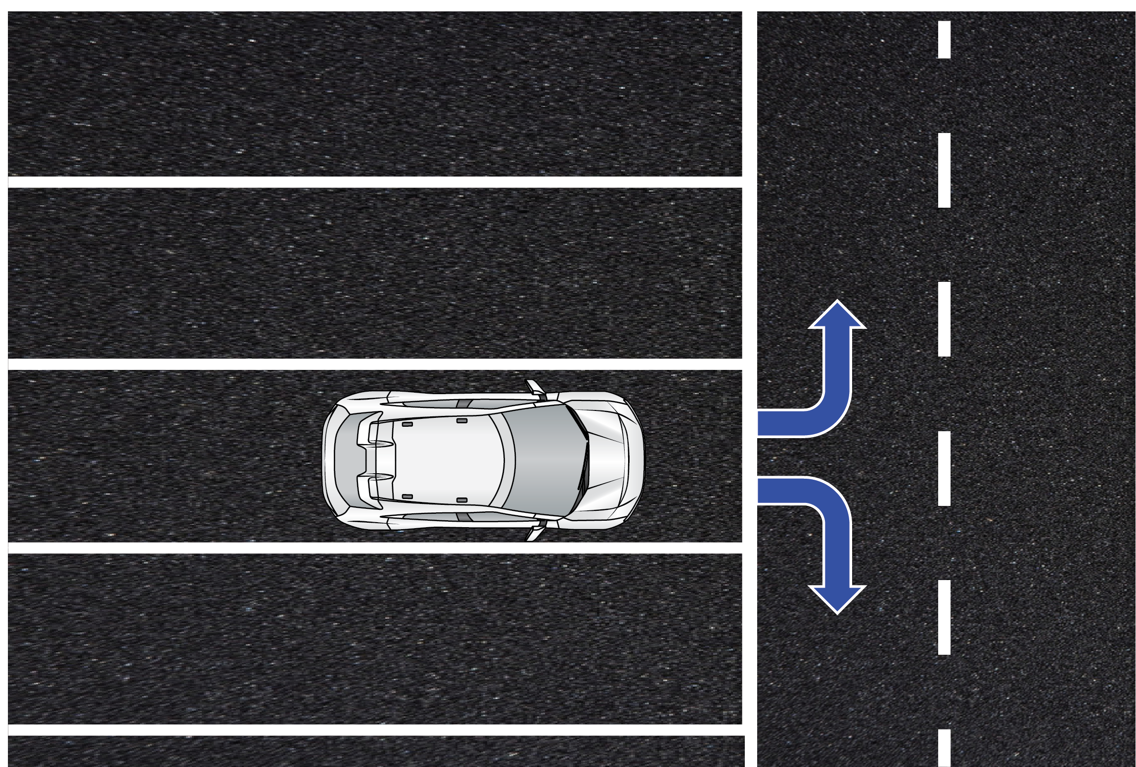
The Lane Keeping Assist System (LKAS) can be turned off by pressing the MAIN or LKAS button on the steering wheel. You can
also change the LKAS setting to turn the suspended beep on or off
Indicates the Vehicle ACC Speed is Increases
Increases the Vehicle ACC Speed is decreases